Automatic control device for medical clinical drainage
An automatic control device and controller technology, which is applied to suction devices, other medical devices, hypodermic injection devices, etc., can solve the problems of increasing the burden on medical staff and patients' families, failing to follow the doctor's expectation, and difficult to guarantee the drainage effect, etc. Achieve the effect of improving safety and stability, ensuring drainage effect, and reducing workload
- Summary
- Abstract
- Description
- Claims
- Application Information
AI Technical Summary
Problems solved by technology
Method used
Image
Examples
Embodiment 1
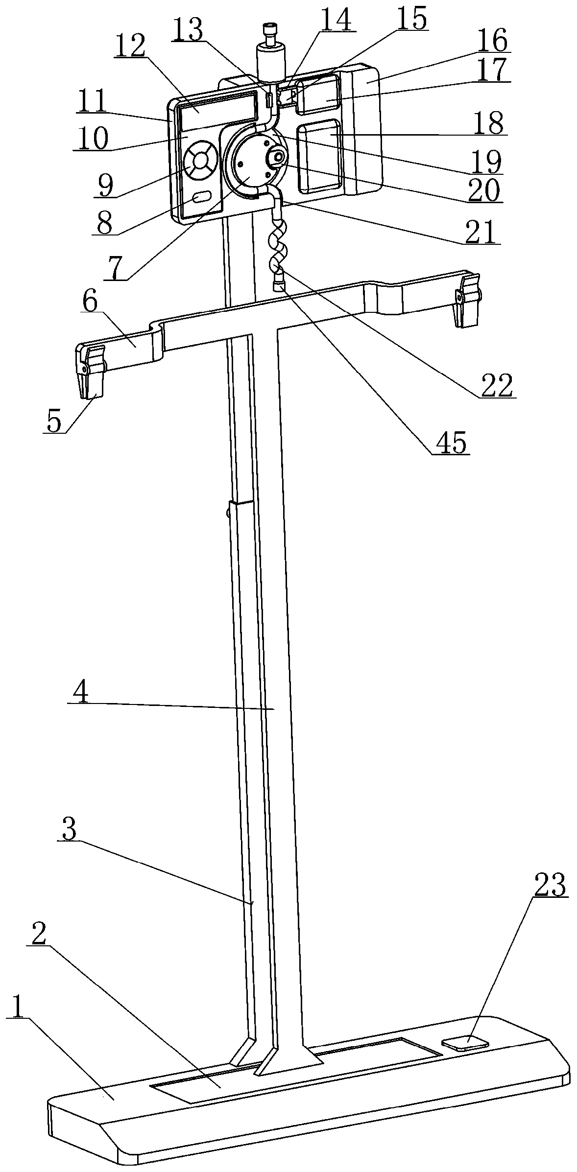
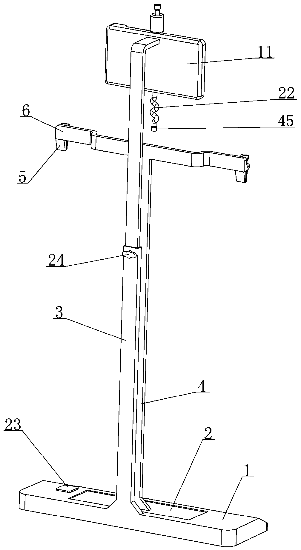
[0041] see figure 1 , 2 , 4, and 6, a medical clinical drainage automatic control device disclosed in this embodiment is composed of a weighing base assembly, a suspension assembly, a seat assembly, a flow rate adjustment mechanism, a negative pressure drainage mechanism, a controller 10 and The power supply assembly 16 consists of several major parts;
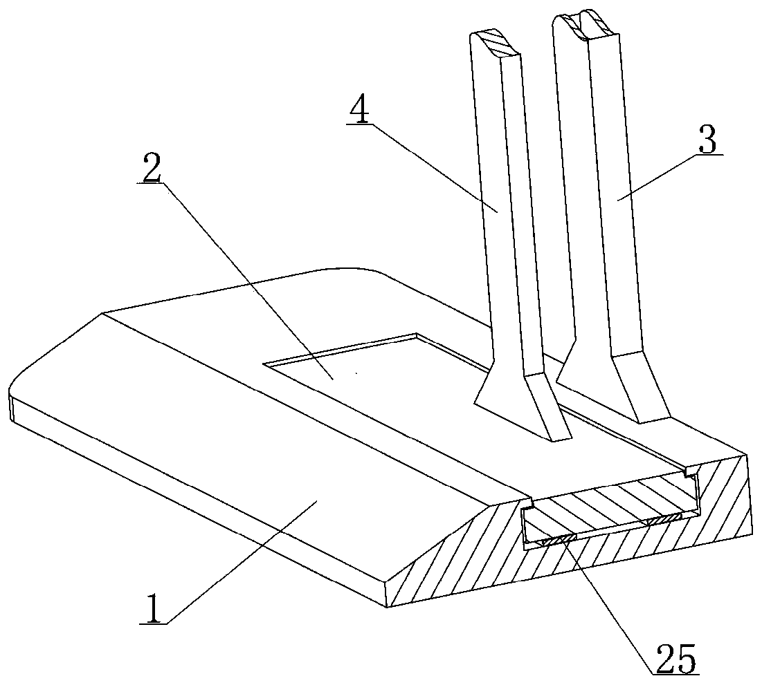
[0042] Among them, see figure 1 , 3 , 5, the weighing base assembly is composed of weighing table 2, load cell 25 and base 1, which are sequentially matched up and down, and the load cell 25 outputs a weighing value that can reflect the weight of the object above the weighing table 2. signal, the base 1 is equipped with a wireless transmission module 23 connected to the load cell 25, a power supply module that provides operating current for the load cell 25 and the wireless transmission module 23;
[0043] Among them, see figure 1 , 2 , 6 and 7, the suspension assembly includes a vertical rod 4 and a suspension beam 6, t...
Embodiment 2
[0073] In the medical clinical drainage automatic control device disclosed in embodiment 1, such as Figure 8 , 9 As shown, the driving device 17 can drive the movable clamp block 15 to move the position based on the control of the controller 10. As far as this technical feature is concerned, the driving device 17 has multiple implementations in the prior art, but in order to make the structure of the driving device 17 Simpler and more compact and more precise in adjusting the position of the movable clamping block 15, this embodiment provides a driving device 17 with a simple structure and stable operation, and its specific implementation structure is as follows:
[0074] see Figure 13 As shown, the driving device 17 includes a motor 35 fixed on the mounting plate 11, the output shaft of the motor 35 is coaxially connected with a screw 34, and a screw hole 33 is provided on the movable clamping block 15, and the movable clamping block 15 passes through The threaded hole 33...
Embodiment 3
[0077] In the medical clinical drainage automatic control device disclosed in embodiment 1, such as Figure 6 , 7 As shown, in the drainage process, the connecting pipe 22 will exert a certain force on the drainage bag 29, although the part of the connecting pipe 22 located between the placement groove 21 and the drainage bag 29 can be in a naturally stretched state by adjusting the placement plate 11 This method is to reduce the force caused by the connecting pipe 22 on the drainage bag 29, but it will inevitably have a certain impact on the data accuracy of the real-time drainage speed and the single real-time drainage volume. In order to make this effect further Reduced, this embodiment also has the following improvements to the connecting pipe 22, the specific structure is:
[0078] see Figure 14 As shown, the middle and lower sections of the connecting pipe 22 are prefabricated with a curved section 36 that is easy to stretch and deform, and the curved section 36 is in...
PUM
 Abstract
Description
Claims
Application Information
 - R&D
- Intellectual Property
- Life Sciences
- Materials
- Tech Scout
- Unparalleled Data Quality
- Higher Quality Content
- 60% Fewer Hallucinations
Browse by: Latest US Patents, China's latest patents, Technical Efficacy Thesaurus, Application Domain, Technology Topic, Popular Technical Reports.
© 2025 PatSnap. All rights reserved.Legal|Privacy policy|Modern Slavery Act Transparency Statement|Sitemap|About US| Contact US: help@patsnap.com


