
Plate rotation type edge sealing band attachment device

A technology of a laminating device and an edge banding strip, which is applied in the field of a plate self-rotating edge banding strip laminating device, can solve the problems of laborious plate movement and the like, and achieve the effect of a simple structure

Inactive Publication Date: 2020-07-17
苏州超烁再生资源有限公司
View PDF0 Cites 1 Cited by
  • Summary
  • Abstract
  • Description
  • Claims
  • Application Information

AI Technical Summary

Problems solved by technology

[0004] The purpose of the present invention is to provide a plate self-rotating type edge banding strip bonding device for the technical problem that the heavy weight of the existing equipment causes the plate to move laboriously

Method used


Image

  • Plate rotation type edge sealing band attachment device
  • Plate rotation type edge sealing band attachment device

Examples


Embodiment Construction

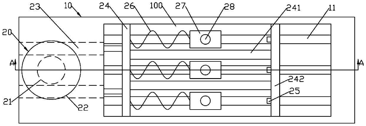
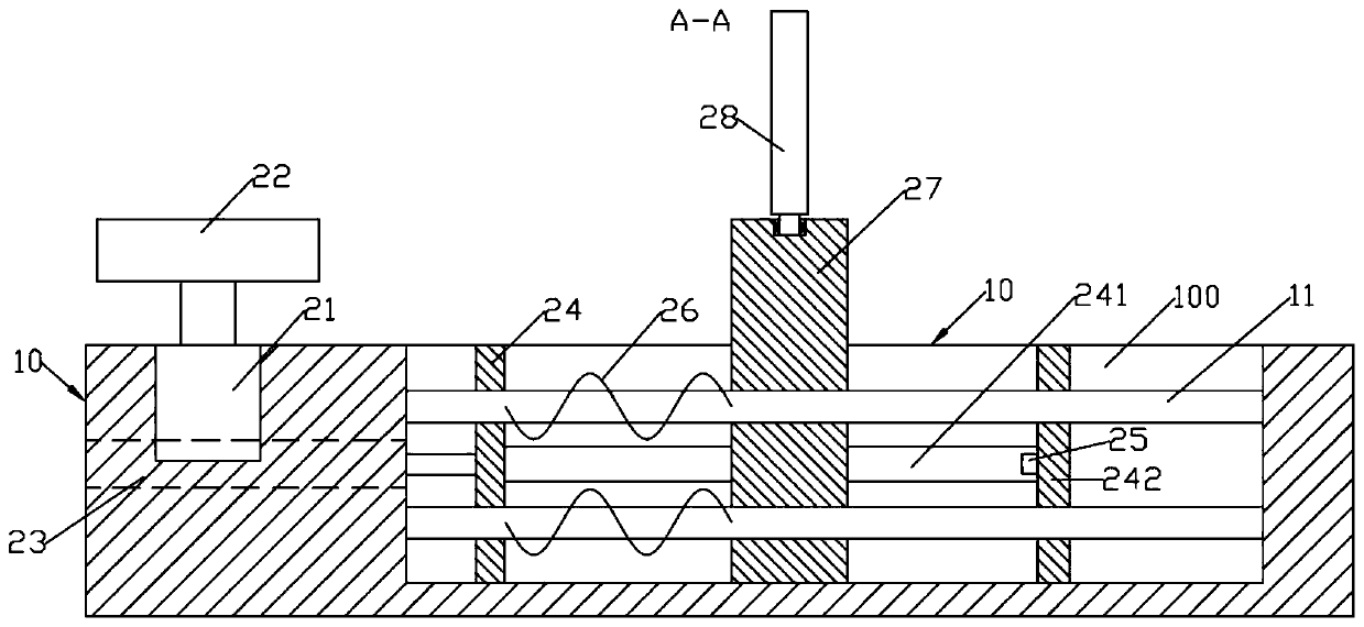
[0015] Such as figure 1 and figure 2 As shown, a sheet metal self-rotating edge banding device includes a cuboid bracket 10 and a self-rotating device 20; the right part of the upper end surface of the bracket 10 is formed with a rectangular fitting slide groove 100; the self-rotating device 20 It includes a supporting plate 22, a sliding limit frame and a number of evenly distributed front and rear left and right sliding support bases 27 arranged in the fitting sliding groove 100; the supporting plate 22 is arranged in the middle of the left end of the upper end surface of the bracket 10 in one-way rotation; the sliding limit frame It includes a left limiting plate 24 that slides left and right and is arranged on the sliding groove 100; several sets of extension spring groups are fixed on the right end surface of the left limiting plate 24; each group of extension spring groups includes a number of extension springs 26 evenly distributed up and down; The right end of extens...


PUM


Abstract

The invention discloses a plate rotation type edge sealing band attachment device. A rectangular attaching slide groove is formed in the right part of the upper end surface of a bracket, a rotation attachment device comprises a support plate, a slide limiting frame and a plurality of supporting bases which are uniformly distributed front and back and arranged in the attaching slide groove in a left-right sliding manner; the support plate is arranged in the middle of the left end of the upper end surface of the bracket in a unidirectional rotating manner; the slide limiting frame comprises a left limiting plate which is arranged in the attaching slide groove in a left-right sliding manner; multiple groups of tension springs are fixed to the right end surface of the left limiting plate; eachgroup of tension springs comprises a plurality of tension springs which are uniformly distributed up and down; right ends of the tension springs are fixed to the left end surfaces of the supporting bases; a plurality of horizontal connecting rods are fixed to the right end surface of the left limiting plate; a right limiting plate is fixed to the right ends of the connecting rods; a plurality ofpressure sensors are mounted on the left end surface of the right limiting plate; and attaching rollers are rotationally arranged on the upper end surfaces of the supporting bases.

Description

technical field [0001] The invention relates to the field of woodworking machinery, in particular to a plate self-rotating edge banding device. Background technique [0002] The section of wooden furniture is usually equipped with edge banding strips to seal the section of the panel to avoid damage to the panel by moisture, and also to prevent the volatilization of formaldehyde inside the panel, while achieving a beautiful decorative effect. Nowadays, edge banding machines or other woodworking machinery with edge banding functions are generally used for sealing, and edge trimming machines are used to trim the edge bands bonded to the board. [0003] The processing of the plate requires the lifting of the plate. In the prior art, the lifting device of the edge banding equipment or the edge trimming equipment that can realize the side processing of the special-shaped plate is a carriage sleeve type or a folded arm type, but the support The weight of the lifting device is rela...

Claims


Application Information

Patent Timeline
Patent Type & Authority Applications(China)
IPC IPC(8): B27N7/00B27D5/00B27M3/18
CPCB27D5/00B27M3/18B27N7/00
Inventor 周世荣
Owner 苏州超烁再生资源有限公司
Learn More