Asphalt pavement flatness detection device

An asphalt pavement and detection device technology, applied in mechanical roughness/irregularity measurement, roads, roads, etc., can solve problems such as affecting the driver's driving experience, causing traffic accidents, and high maintenance costs, achieving applicability and flexibility. The effect of improving performance and reducing workload

Active Publication Date: 2020-07-17
张宏伟
View PDF5 Cites 29 Cited by
  • Summary
  • Abstract
  • Description
  • Claims
  • Application Information

AI Technical Summary

Problems solved by technology

[0002] In modern highway construction, asphalt pavement is widely used in high-grade highways due to its short construction period, high driving comfort, low noise, and easy maintenance in the later stage. However, high-grade asphalt pavement requires high flatness. Inspectors need to follow up the inspection and acceptance in time, establish a database of asphalt pavement flatness, and provide a basis for subsequent construction and quality rectification. Asphalt pavement is prone to defects such as rutting, sinking and deformation, and wrapping, which will lead to a decrease in the smoothness of the road surface, affecting the driving experience of drivers and passengers, and even causing traffic accidents in severe cases;
[0003] Traditional road surface roughness detection devices include: uniaxial acceleration sensor, laser ranging sensor and odometer sensor, but the structure of traditional measuring device is complicated and the cost of use is high. It is easy to be damaged during the process, and once damaged, it will bring high maintenance costs;
[0004] Alternatively, traditional mechanical measurement methods are used to measure the flatness of the road surface, such as the 3-meter ruler method, but this method is relatively backward and the measurement efficiency is low. The operator needs to bow his head and bend over when measuring. The ups and downs change is not very large, and the road surface roughness information measured by the above method cannot amplify the real ups and downs of the road surface, that is, it is difficult for the surveyor to clearly and intuitively see the roughness information of the road;

Method used


Image

  • Asphalt pavement flatness detection device
  • Asphalt pavement flatness detection device
  • Asphalt pavement flatness detection device

Examples


Embodiment 1

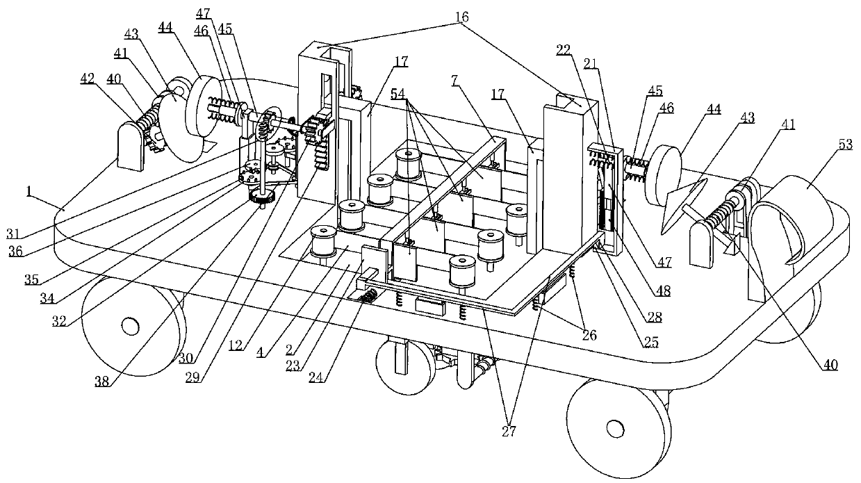
[0040] Embodiment 1, this embodiment provides a kind of asphalt pavement roughness detection device, refer to the attached figure 1 As shown, it includes a dolly 1, the bottom of the dolly 1 is rotated on both sides laterally, and a wheel axle 5 is installed on the wheel axle 5, and a hook 53 is fixed at one end of the dolly 1 in the transverse direction. When the detection device is working, we The detection vehicle drags the trolley 1 through the hook 53 to run at a constant speed along the detection road at a set speed;

[0041] We vertically slide and install a bearing plate 2 on the trolley 1, and a detection unit vertically slidably installed on the bearing plate 2 is arranged at longitudinal intervals on the bearing plate 2, and a compression spring 3 is connected between the detection unit and the bearing plate 2 , when the trolley 1 drives at a constant speed under the drag of the detection vehicle, several detection units keep in close contact with the ground under t...

Embodiment 2

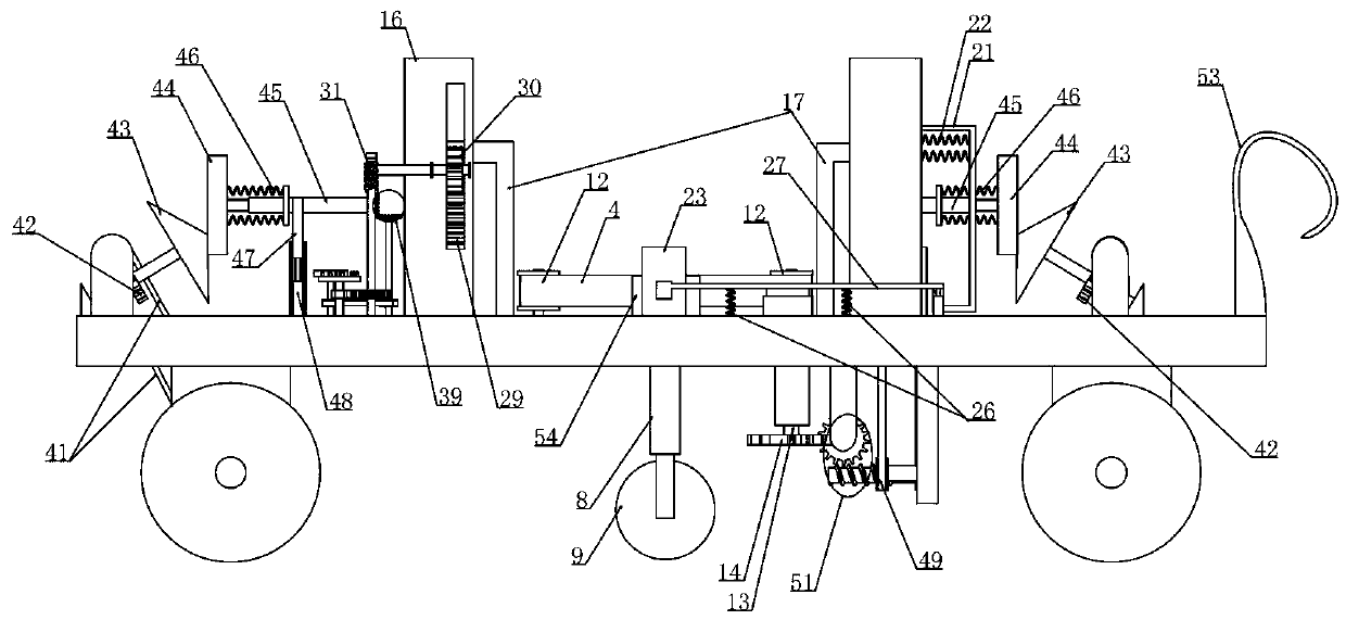
[0050] Embodiment 2, on the basis of embodiment 1, with reference to appended Figure 8 As shown, the detection unit includes a detection frame 8 arranged at intervals in the longitudinal direction and vertically slidably installed on the bearing plate 2, referring to the attached Figure 7 As shown, the compression spring 3 is connected between the bearing plate 2 and the detection frame 8, and under the elastic force of the compression spring 3, the detection wheel 9 is tightly against the road surface. When the trolley 1 is dragged by the detection vehicle When advancing along the detected road, a plurality of detection wheels 9 are synchronously driven to rotate, and when the detection wheels 9 move to the position where there are potholes or protrusions on the road surface, the detection frame 8 is driven by the detection wheels 9 to move vertically along the bearing plate 2. move, see attached Figure 8 As shown, the upper end of the detection frame 8 is vertically slid...

Embodiment 3

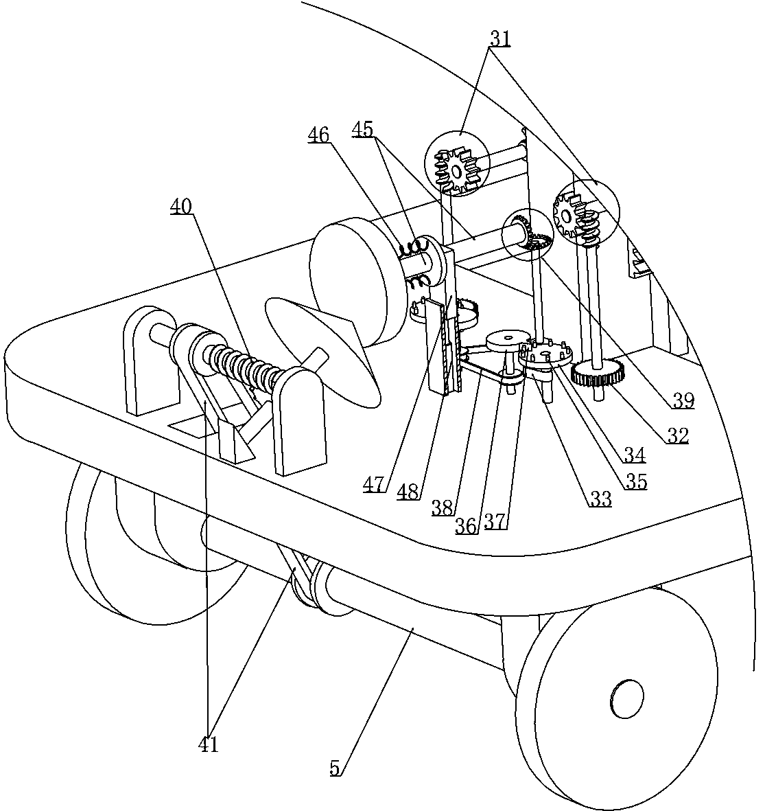
[0051] Embodiment 3, on the basis of embodiment 1, with reference to appended Figure 8 As shown, one of the reels 12 in each group of the reels 12 is coaxially rotated and fitted with a transmission cylinder 13 rotatably mounted on the trolley 1, and the axial sliding fit between the transmission cylinder 13 and the shaft of the reel 12 is Therefore, the axial sliding fit between the reel 12 shaft and the transmission cylinder 13 is set to cooperate with the vertical movement of the bearing plate 2, so that the reel 12 shaft and the corresponding transmission cylinder 13 can always realize power transmission ;

[0052] The first transmission device includes a first worm wheel 14 that rotates coaxially with the transmission cylinder 13, and a plurality of the first worm wheels 14 are meshed with a first worm 15 that is rotatably mounted on the trolley 1, and the first worm 15 passes through the first worm wheel 14. Driven by a speed regulating device, the wheels of the trolle...


PUM


Abstract

The invention relates to an asphalt pavement flatness detection device. The problems that an existing pavement flatness detection device is tedious in measurement and large in workload of detection personnel are effectively solved. According to the technical scheme, the detected pavement flatness information condition can be amplified in a corresponding proportion by the device so that measurementpersonnel can clearly and visually see the flatness information of the pavement; and through cooperation of an intermittent transmission mechanism arranged on a trolley and a second transmission device, the detection device completes spot check and detection of the pavement surface flatness at specific intervals, namely, automatic detection of pavement flatness information is achieved, the workload of detection personnel is greatly reduced, and the device is convenient to use and can be widely applied and popularized.

Description

technical field [0001] The invention relates to the technical field of road construction detection, in particular to an asphalt pavement smoothness detection device. Background technique [0002] In modern highway construction, asphalt pavement is widely used in high-grade highways due to its short construction period, high driving comfort, low noise, and easy maintenance in the later stage. However, high-grade asphalt pavement requires high flatness. Inspectors need to follow up the inspection and acceptance in time, establish a database of asphalt pavement flatness, and provide a basis for subsequent construction and quality rectification. Asphalt pavement is prone to defects such as rutting, sinking and deformation, and wrapping, which will lead to a decrease in the smoothness of the road surface, affecting the driving experience of drivers and passengers, and even causing traffic accidents in severe cases; [0003] Traditional road surface roughness detection devices in...

Claims


Application Information

Patent Timeline
Patent Type & Authority Applications(China)
IPC IPC(8): E01C23/01G01B5/28G01B5/20
CPCE01C23/01G01B5/20G01B5/28
Inventor 张宏伟金涛雷亚利刘朝伟田素英王雨佳王翠峥郝丹丹
Owner 张宏伟
Why Eureka
Try Eureka