Rapid dredging device for hydraulic engineering and implement method thereof
A dredging device and water conservancy engineering technology, applied in the direction of earth mover/shovel, mechanically driven excavator/dredger, construction, etc., can solve the problems of bulky, inoperable, inflexible and convenient to use, etc. To achieve the effect of improving the dredging efficiency
- Summary
- Abstract
- Description
- Claims
- Application Information
AI Technical Summary
Problems solved by technology
Method used
Image

Examples
Embodiment 1
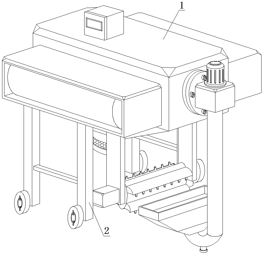
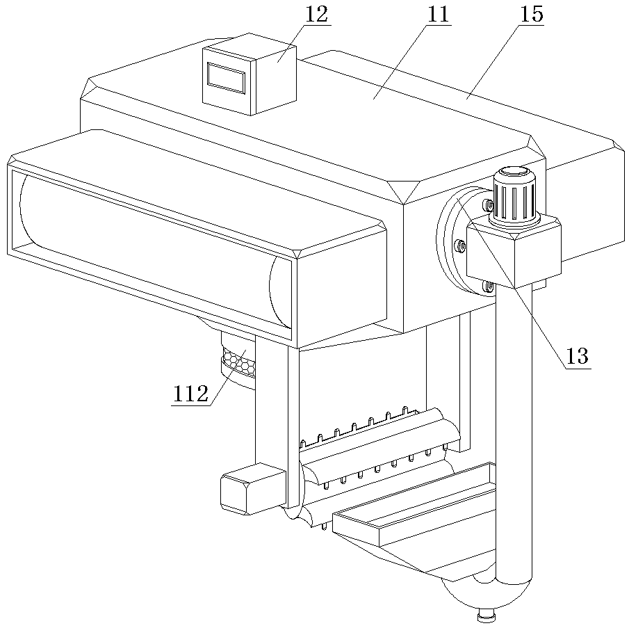
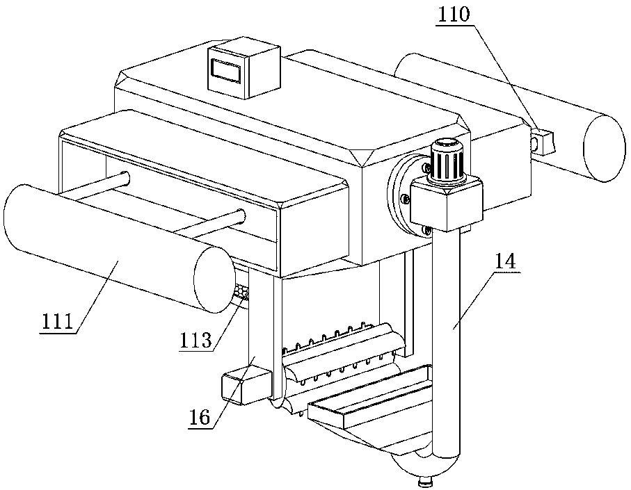
[0038] Example 1: Please refer to Figure 1-4 , a rapid desilting device for water conservancy projects, comprising a cleaning device 1 and a supporting device 2, the supporting device 2 is arranged at the bottom of the cleaning device 1, and the cleaning device 1 includes a dredging bin 11, a control box 12, a mud inlet port 13, and a conveying mechanism 14. Storage box 15 and dredging mechanism 16, a control box 12 is set on the top side of the dredging bin 11, a touch screen controller is set on the side wall of the control box 12, and a battery is installed inside the control box 12, and One end of the dredging bin 11 is provided with a mud inlet port 13 on the outer wall of the mud inlet port 13, and a conveying mechanism 14 is fixedly connected to the outer wall of the mud inlet port 13. An integrated structure is formed between the box 15 and the dredging bin 11 , and a dredging mechanism 16 is installed on the bottom of the storage box 15 near the side of the conveying...
Embodiment 2
[0040] Example 2: Please refer to figure 1 and Figure 9 , a rapid dredging device for water conservancy projects, the supporting device 2 includes a connecting plate 21, a supporting column 22, a cross bar 23, a connecting rod 24 and a roller 25, and the connecting plate 21 is respectively arranged on the receiving sides of the dredging mechanism 16 through fixing bolts. At the bottom of the box 15, the two sides of the lower end of the connecting plate 21 are respectively fixedly connected with support columns 22, and a cross bar 23 is arranged between the side walls of the adjacent support columns 22 on the same side, and the connecting rods 24 are respectively fixedly connected to the support columns 22 away from the dredging. The outer wall on one side of the mechanism 16 is close to the bottom, and the outer wall of the connecting rod 24 is sleeved with rollers 25. Using the rolling ability of the rollers 25, it is convenient to push and transport the equipment to the wo...
Embodiment 3
[0041] Example 3: Please refer to image 3 and Figure 5 , a quick dredging device for water conservancy projects, the conveying mechanism 14 includes a connecting box 141, a flange 142, a conveying pipe 143, a driving motor 144, a screw A145 and an auger 146, and a port is provided on one side of the connecting box 141, and the port A flange 142 is fixedly connected to the outer wall of the body, and the communication box 141 is fixedly connected to the outer wall of the mud inlet port 13 through the cooperation of the flange 142 and the fixing bolt. The bottom of the communication box 141 is provided with a delivery pipe 143, and the drive motor 144 is installed On the top of the communication box 141, the drive motor 144 is electrically connected to the control box 12, and the bottom output end of the drive motor 144 is fixedly connected to one end of the screw A145, and the other end of the screw A145 runs through the top of the communication box 141 and extends downward t...
PUM
 Abstract
Description
Claims
Application Information
 - R&D
- Intellectual Property
- Life Sciences
- Materials
- Tech Scout
- Unparalleled Data Quality
- Higher Quality Content
- 60% Fewer Hallucinations
Browse by: Latest US Patents, China's latest patents, Technical Efficacy Thesaurus, Application Domain, Technology Topic, Popular Technical Reports.
© 2025 PatSnap. All rights reserved.Legal|Privacy policy|Modern Slavery Act Transparency Statement|Sitemap|About US| Contact US: help@patsnap.com