Punching equipment for bridge construction site

A technology for drilling equipment and bridge construction, applied in drilling equipment and methods, drilling equipment, construction, etc., can solve problems such as affecting the service life of drill bits, inconvenient use of drilling equipment, and inability to cool drill bits and stems, saving manpower , Avoid hand-held punching, easy to operate effect

Inactive Publication Date: 2020-07-17
罗峰
View PDF7 Cites 6 Cited by
  • Summary
  • Abstract
  • Description
  • Claims
  • Application Information

AI Technical Summary

Problems solved by technology

[0004] The purpose of the present invention is to solve the shortcomings of the existing drilling equipment for bridge construction, such as inconvenient use, time-consuming and laborious, low work efficiency, and inability to cool down the drill rod, which affects the service life of the drill rod and delays the work progress. Drilling equipment for bridge construction site

Method used


Image

  • Punching equipment for bridge construction site
  • Punching equipment for bridge construction site
  • Punching equipment for bridge construction site

Examples


Embodiment 1

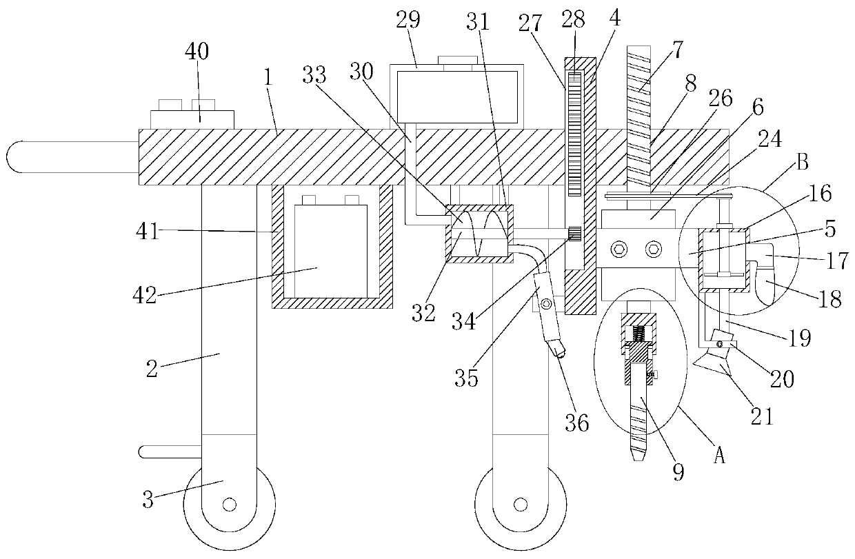
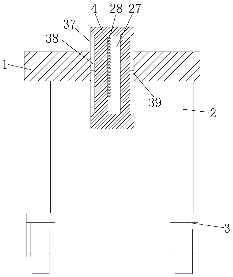
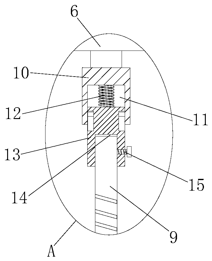
[0030] refer to Figure 1-5 , a drilling device for a bridge construction site, comprising a top plate 1, four support legs 2 are fixedly installed on the bottom of the top plate 1, universal wheels 3 are arranged on the bottom of the four support legs 2, and a vertical sliding device is installed on the top plate 1 Vertical plate 4, a motor mounting plate 5 is fixedly installed on one side of the vertical plate 4, a double-head motor 6 is arranged on the motor mounting plate 5, and a lifting screw 7 is fixedly installed on an output shaft of the double-head motor 6, and on the top plate 1 There is a lifting screw hole 8, the lifting screw rod 7 is threadedly connected with the lifting screw hole 8, a buffer structure is fixedly installed on the other output shaft of the double-head motor 6, a drill rod 9 is installed on the buffer structure, and one side of the motor mounting plate 5 The dust suction structure is fixedly connected with the lifting screw 7, the top of the top ...

Embodiment 2

[0041] refer to Figure 1-5 , a drilling device for a bridge construction site, comprising a top plate 1, four support legs 2 are fixedly installed on the bottom of the top plate 1 by welding, universal wheels 3 are arranged on the bottom of the four support legs 2, and the top plate 1 slides vertically A vertical plate 4 is installed, and one side of the vertical plate 4 is fixedly installed with a motor mounting plate 5 by welding. The motor mounting plate 5 is provided with a double-head motor 6, and an output shaft of the double-head motor 6 is fixedly installed with a lift by welding. The screw rod 7 is provided with a lifting screw hole 8 on the top plate 1, and the lifting screw rod 7 is threadedly connected with the lifting screw hole 8. A buffer structure is fixedly installed on the other output shaft of the double-head motor 6 by welding, and a drill rod 9 is installed on the buffer structure. One side of the motor mounting plate 5 is fixedly installed with a dust su...


PUM


Abstract

The invention belongs to the technical field of bridge construction, and particularly relates to punching equipment for a bridge construction site. The punching equipment is put forward to solve the problems that existing punching equipment for bridge construction is inconvenient to use, the time and labor are wasted, the working efficiency is low, a drill rod cannot be cooled, the service life ofthe drill rod is affected, and job schedule is influenced. The punching equipment comprises a top plate, wherein four supporting legs are fixedly installed at the bottom of the top plate, universal wheels are arranged at the bottoms of the four supporting legs, a perpendicular plate is vertically and slidably installed on the top plate, a motor installing plate is fixedly installed at one side ofthe perpendicular plate, a double-end motor is arranged on the motor installing plate, a lifting screw rod is fixedly installed on an output shaft of the double-end motor, a lifting screw hole is formed in the top plate, and the lifting screw rod is in threaded connection with the lifting screw hole. The punching equipment is convenient to operate, manual punching is avoided, the labor is saved,and the working efficiency is improved; and meanwhile, the punching equipment has the effects of collecting dust and cooling the drill rod, so that the situation that the temperature rise of the drillrod influences the service life of the drill rod is avoided.

Description

technical field [0001] The invention belongs to the technical field of bridge construction, and in particular relates to a drilling device for a bridge construction site. Background technique [0002] A bridge refers to a building erected on rivers, lakes and seas to enable the smooth passage of vehicles and pedestrians. It is called a bridge. A bridge is generally composed of a superstructure, a substructure, a support and ancillary structures. The superstructure is also called a bridge span structure, which is the main structure for crossing obstacles; the substructure includes abutments, piers and foundations; Or the force transmission device installed at the supporting place of the bridge abutment; the auxiliary structures refer to the bridge head board, conical slope protection, revetment and diversion engineering, etc. In the bridge construction project, drilling equipment is needed. Finally, guardrails need to be installed on the bridge deck and holes need to be dril...

Claims


Application Information

Patent Timeline
Patent Type & Authority Applications(China)
IPC IPC(8): E21B7/02E21B3/02E21B19/081E21B17/04E21B17/07E21B21/07E21B12/00
CPCE21B3/02E21B7/024E21B12/00E21B17/04E21B17/07E21B19/081E21B21/07
Inventor 罗峰
Owner 罗峰
Why Eureka
Try Eureka