Industrial robot pose measurement target device and joint position sensitive error calibration method

An industrial robot and pose measurement technology, which is applied in the direction of measuring devices, optical devices, instruments, etc., can solve the problems of high price of special targets and reduce the efficiency of pose measurement of industrial robots, so as to improve the global accuracy and realize automatic pose The effect of small measurement and calculation errors

Active Publication Date: 2020-07-17
NANJING INST OF TECH
View PDF4 Cites 8 Cited by
  • Summary
  • Abstract
  • Description
  • Claims
  • Application Information

AI Technical Summary

Problems solved by technology

To realize the measurement of the end pose of the robot, a special target is required, but the price of the special target is higher
In addition, three target balls can be used to construct a coordinate system, but because the laser tracker cannot automatically identify the target ball, manual intervention is required in the measurement process, which will greatly reduce the efficiency of industrial robot pose measurement, and also introduce certain measurement uncertainty

Method used


Image

  • Industrial robot pose measurement target device and joint position sensitive error calibration method
  • Industrial robot pose measurement target device and joint position sensitive error calibration method
  • Industrial robot pose measurement target device and joint position sensitive error calibration method

Examples


Embodiment Construction

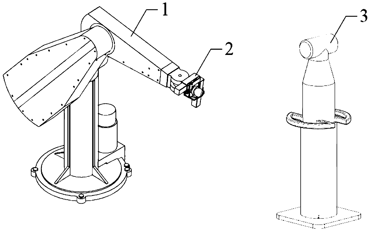
[0045] now combined with Figure 1-4 The present invention is described in further detail.

[0046] Such as figure 1As shown, in one embodiment of the present invention, an industrial robot 1 pose measurement target device includes a laser tracker 3 and a terminal pose measurement target device 2, and the terminal pose measurement target device 2 is located in an industrial At the end of the robot 1 , the laser tracker 3 is arranged on one side of the industrial robot 1 , and the laser tracker 3 is used to measure the spatial pose of the target ball 206 in the end pose measurement target device 2 .

[0047] In this embodiment, the end pose measurement target device 2 is installed on the flange of the industrial robot 1, that is, the end of the industrial robot 1, and the laser tracker 3 measures the spatial pose of the target ball 206 in the end pose measurement target device 2 .

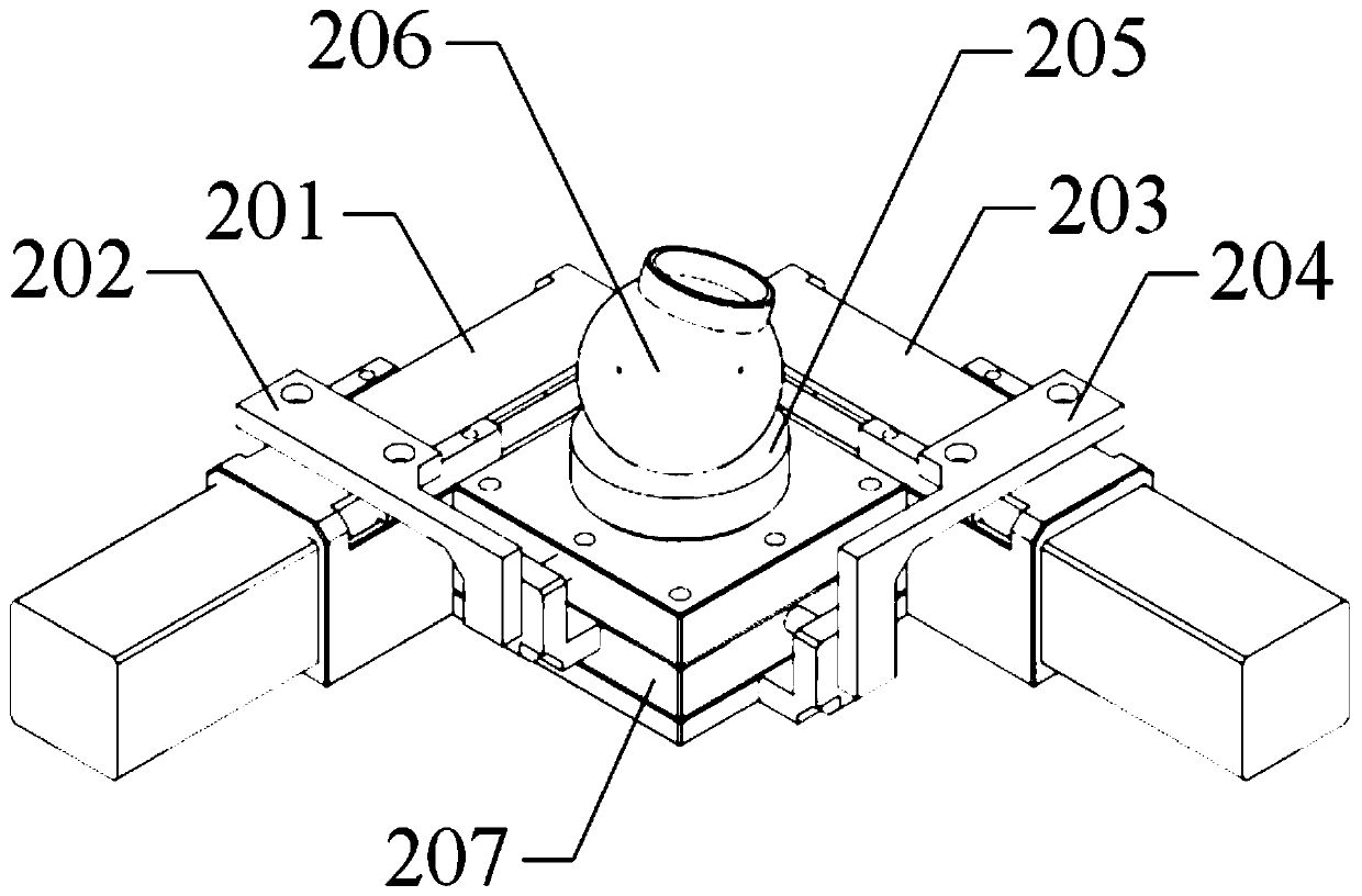
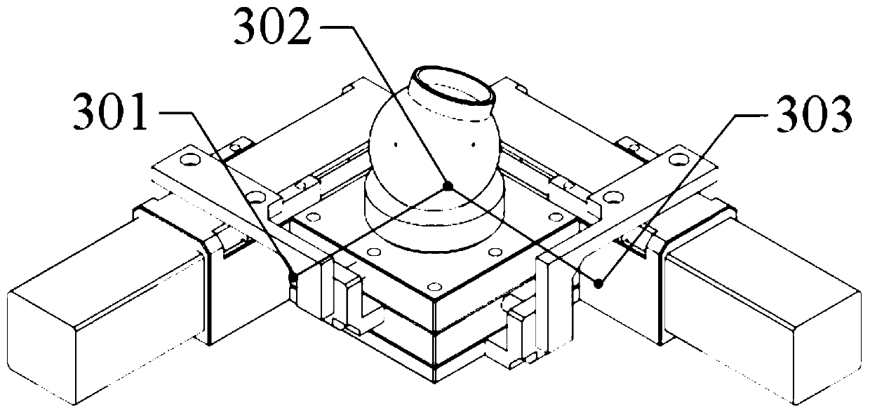
[0048] Such as figure 2 with image 3 As shown, in one of the embodiments of the present i...


PUM


Abstract

The invention discloses an industrial robot pose measurement target device and a joint position sensitive error calibration method. The system comprises a laser tracker and a tail end pose measurementtarget device, the tail end pose measurement target device is arranged at a tail end of an industrial robot, the laser tracker is arranged on one side of the industrial robot, and the laser tracker is used for measuring the spatial position of a target ball in the tail end pose measurement target device. Only three points need to be measured in the measurement process, the introduced calculationerror is small, the pose measurement precision is high, the automatic pose measurement can be achieved, and compared with a special target, the cost is low. According to the method, the characteristics of the error source of the industrial robot are fully considered, the regional problem of a traditional calibration method based on an error model is solved, and the global precision of the robot iseffectively improved.

Description

technical field [0001] The invention belongs to the technical field of industrial robot parameter calibration, in particular to an industrial robot pose measurement target device and a joint position sensitive error calibration method. Background technique [0002] As a symbol of the rise of industry and a measure of a country's international competitiveness, high-end manufacturing equipment reflects the core competitiveness of a country. With the development of robot technology, industrial robots are more and more widely used in high-end manufacturing fields, such as hole making / riveting in the aerospace industry, wind power blade grinding, etc. These application fields require high absolute positioning accuracy of industrial robots. Studies have shown that the positioning error of industrial robots is mainly caused by geometric parameter errors and non-geometric parameter errors. Among them, the geometric parameter error accounts for about 90% of the total error. It is ge...

Claims


Application Information

Patent Timeline
Patent Type & Authority Applications(China)
IPC IPC(8): G01B11/00G01C25/00
CPCG01B11/00G01C25/00
Inventor 乔贵方孙大林温秀兰宋光明张颖万其
Owner NANJING INST OF TECH
Why Eureka
Try Eureka