Temperature correction method, device and system
A correction value and temperature value technology, applied in the computer field, can solve the problem of low accuracy of temperature measurement results and achieve the effect of improving accuracy
- Summary
- Abstract
- Description
- Claims
- Application Information
AI Technical Summary
Problems solved by technology
Method used
Image

Examples
Embodiment 1
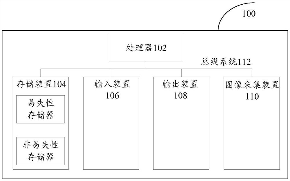
[0034] First, refer to figure 1 An example electronic device 100 for implementing the temperature correction method, device and system of the embodiments of the present invention will be described.
[0035] Such as figure 1 Shown is a schematic structural diagram of an electronic device. The electronic device 100 includes one or more processors 102, one or more storage devices 104, an input device 106, an output device 108, and an image acquisition device 110. These components pass through a bus system 112 and / or other forms of connection mechanisms (not shown). It should be noted that figure 1 The components and structure of the electronic device 100 shown are only exemplary, not limiting, and the electronic device may have figure 1 Some components shown may also have figure 1 Other components and structures not shown.
[0036] The processor 102 may be a central processing unit (CPU) or other forms of processing units with data processing capabilities and / or instruction ...
Embodiment 2
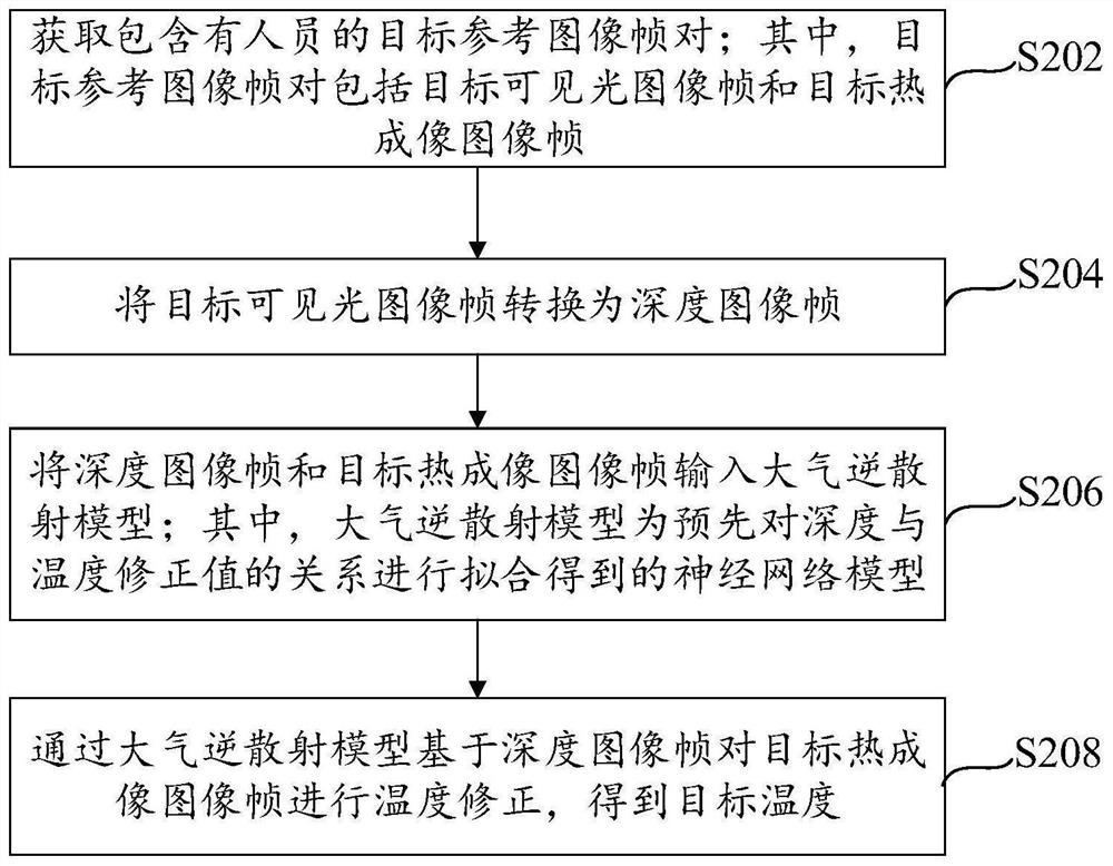
[0043] refer to figure 2 A flow chart of a temperature correction method is shown, the method mainly includes the following steps S202 to S208:
[0044] Step S202, acquiring a target reference image frame pair including a person; wherein, the target reference image frame pair can be obtained by collecting images of the person in the monitoring area by a dual-light camera. The dual-light camera is a combined camera with a dual-camera structure. The dual-light camera in this embodiment is a combination of a visible light camera and a thermal imaging camera. The target visible light image frame containing personnel collected by the visible light camera and the target thermal imaging image frame containing personnel collected by the thermal imaging camera correspond to each other to form a target reference image frame pair.
[0045] Step S204, converting the target visible light image frame into a depth image frame. In an implementation manner, the target visible light image fr...
Embodiment approach
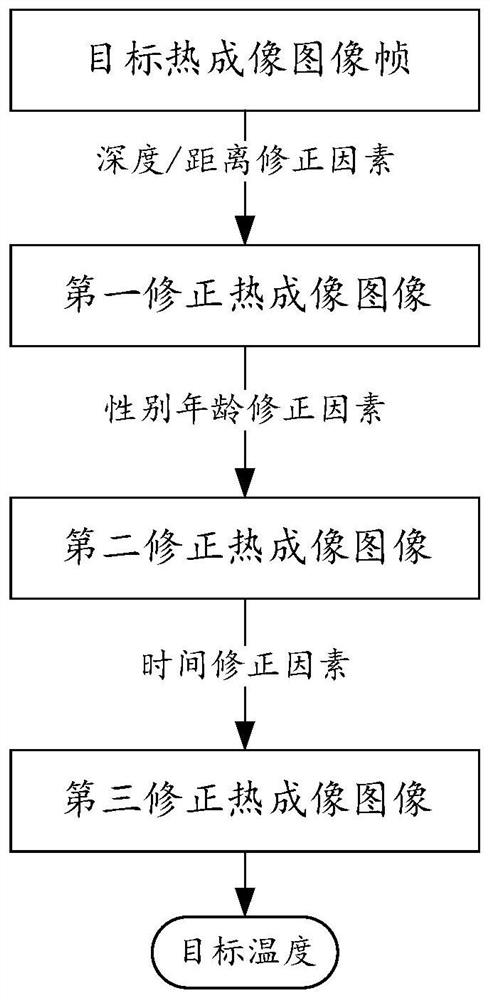
[0068] For ease of understanding, refer to image 3 , here is an optional implementation of temperature correction of the target thermal imaging image frame according to the first temperature correction value and the preset temperature correction factor, referring to the following steps 1 and 2:
[0069] Step 1: Correct the pixel temperature value in the positioning frame of the target thermal imaging image frame according to the first temperature correction value to obtain the first corrected thermal imaging image frame of the target thermal imaging image frame; the above positioning frame is based on the positioning of the target person Information is determined.
[0070] In the specific implementation, first, the pixel temperature value in the positioning frame of the target thermal imaging image frame is corrected according to the first temperature correction value, and the corrected pixel temperature value in the positioning frame of the target thermal imaging image frame...
PUM
 Abstract
Description
Claims
Application Information
 - R&D
- Intellectual Property
- Life Sciences
- Materials
- Tech Scout
- Unparalleled Data Quality
- Higher Quality Content
- 60% Fewer Hallucinations
Browse by: Latest US Patents, China's latest patents, Technical Efficacy Thesaurus, Application Domain, Technology Topic, Popular Technical Reports.
© 2025 PatSnap. All rights reserved.Legal|Privacy policy|Modern Slavery Act Transparency Statement|Sitemap|About US| Contact US: help@patsnap.com