Eureka AIR delivers breakthrough ideas for toughest innovation challenges, trusted by R&D personnel around the world.

Auxiliary structure for adhesive connection of metal bipolar plate flow field area of fuel cell

A metal bipolar plate and fuel cell technology, which is applied in the direction of fuel cell additives, fuel cell parts, fuel cells, etc., can solve the problems of plate function failure, welding without welding area, and affecting the flatness of the plate. Achieve the effect of increasing flow resistance and improving bonding performance

Pending Publication Date: 2020-07-17
SHANGHAI ZHIZHEN NEW ENERGY EQUIP CO LTD
View PDF0 Cites 1 Cited by
  • Summary
  • Abstract
  • Description
  • Claims
  • Application Information

AI Technical Summary

Problems solved by technology

[0003] At present, the mainstream forming process of metal bipolar plates is to use welding to weld two unipolar plates together to form bipolar plates. There are some unavoidable problems in this forming process. For example, the problem of welding thermal deformation will affect the flatness of the plates. A small welding area will lead to weak welding or welding penetration, which will lead to the failure of the function of the plate
[0004] Due to the narrow welding area, when the positioning of the electrode plate or the position of the laser welding head is misaligned, the welding position will appear on the wall of the flow channel, and no effective welding is performed in the welding area, resulting in the failure of the plate function

Method used


Image

  • Auxiliary structure for adhesive connection of metal bipolar plate flow field area of fuel cell
  • Auxiliary structure for adhesive connection of metal bipolar plate flow field area of fuel cell

Examples


Embodiment Construction

[0014] In order to make the technical means, creative features, goals and effects achieved by the present invention easy to understand, the present invention will be further elaborated below in conjunction with illustrations and specific embodiments.

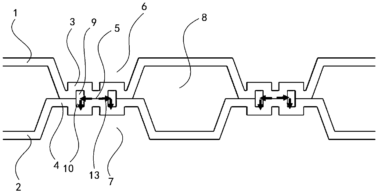
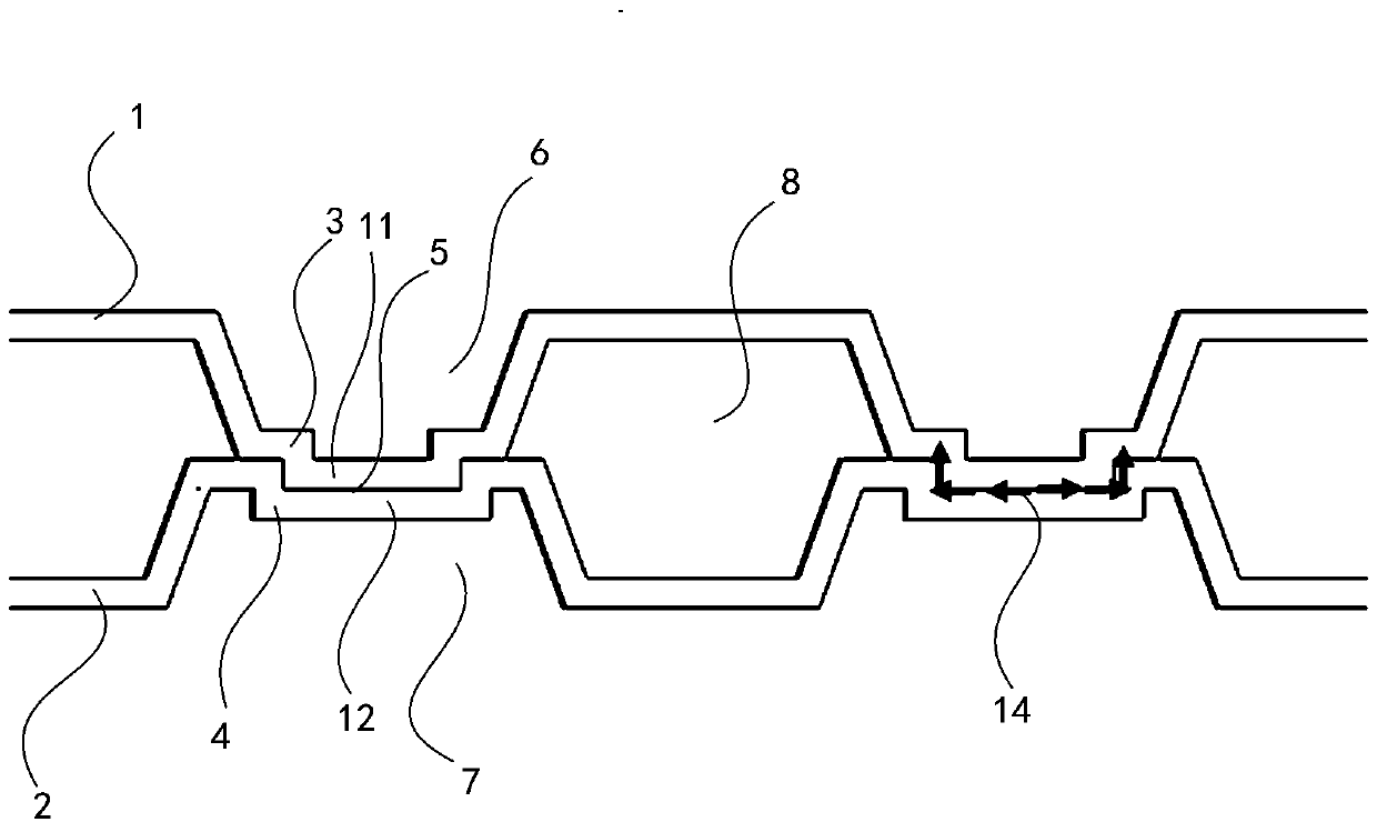
[0015] The invention discloses an auxiliary structure for the adhesive connection of the flow field area of ​​the metal bipolar plate of the fuel cell, such as figure 1 As shown in , it is the first embodiment of the present invention, which is different from the prior art in that: it includes an anode plate 1 and a cathode plate 2, and the anode plate 1 forms several raised forward flow lines toward the cathode plate 2. The channel ridges 3, the cathode plate 2 form a number of reverse channel ridges 4 that protrude in the direction of the anode plate 1, and the forward channel ridges 3 and the reverse channel ridges 4 are distributed in one-to-one correspondence The contact surface of the forward flow channel ridge 3 and the r...


PUM


Abstract

The invention discloses an auxiliary structure for adhesive connection of a metal bipolar plate flow field area of a fuel cell. A plurality of convex forward runner ridges are formed on the an anode plate towards the a cathode plate; the cathode plate forms a plurality of reverse runner ridges protruding in the reverse direction are formed on the cathode plate towards the anode plate, the forwardrunner ridges and the reverse runner ridges are distributed in a one-to-one correspondence mode, the contact faces of the forward runner ridges and the reverse runner ridges form a runner ridge gluingarea, and mucilage glue is applied to the runner ridge gluing area. The auxiliary structure device has the beneficial effects that glue overflowing from the gluing area of the runner ridge can be efficiently stored, and the bonding performance is improved; a concave-convex matching structure is designed in ridge areas of cathode and anode runners, so that the flowing resistance of mucilage glueis increased by a the formed fine path, and excessive colloid is prevented from overflowing into a cooling liquid cavity to influence the performance of the polar plate; due to stamping forming of thecathode and anode runner ridge glue containing structure, a the protruding area is formed at the bottom of the runner groove, a flow guiding effect is achieved on gas flowing is realized, and gas canbe promoted to be conveyed to a catalytic layer.

Description

technical field [0001] The invention relates to the technical field of metal bipolar plates, in particular to an auxiliary structure for the adhesive connection of the flow field area of ​​the metal bipolar plate of a fuel cell, and particularly relates to its mechanical connection structure. Background technique [0002] Fuel cell is a device that uses hydrogen and oxygen fuel to generate electricity through electrochemical combination. It has the advantages of high efficiency, high power density, and low to zero emissions, and has become a feasible power generation technology in the future. A fuel cell is a system that integrates multiple components, including bipolar plates, proton exchange membranes, and catalytic layers. As one of the key components, bipolar plates play the roles of support, flow collection, and water management. The mainstream bipolar plates include metal bipolar plates, graphite bipolar plates and composite bipolar plates. [0003] At present, the ma...

Claims


Application Information

Patent Timeline
IPC IPC(8): H01M8/026H01M8/0267H01M8/04082H01M8/04089
CPCH01M8/026H01M8/0267H01M8/04089H01M8/04201Y02E60/50
Inventor 姜天豪王鹏毕飞飞杜祥永彭林法蓝树槐
Owner SHANGHAI ZHIZHEN NEW ENERGY EQUIP CO LTD
Why Eureka
Eureka Blog
Learn More