Cable joint connection branch box

A technology of cable joints and branch boxes, applied in the direction of cable joints, etc., can solve the problems of no isolation protection, cable damage to the cable head, etc., achieve beautiful appearance, improve construction efficiency, and shorten the construction period

Pending Publication Date: 2020-07-17
SHENGLI OILFIELD HENGYUAN ELECTRIC +1
0 Cites 0 Cited by

AI-Extracted Technical Summary

Problems solved by technology

There are no isolation protection measures between the phase sequences of the cable connec...

Method used

[0021] Afterwards, the cable is fixed on the cable fixing beam 11 with a supporting cable fixing fixture. High-voltage cable inlet 9 is sealed with insulating plate and fixed with bolts. In this way, the whole high-voltage cable joint is above the ground, which is convenient for inspection and maintenance through the inspection door 8 and the passage door 10, and the construction in the box is safe and convenient. It can be seen that the invention and utilization of the branch box fo...

Abstract

The invention provides a cable joint connection branch box. A box body top cover, a box body frame, a cable joint support and a skid-mounted chassis are formed by welding galvanized profiles. The boxbody top cover is located at the top end of the branch box, the cable joint support is fixed to the skid-mounted chassis, and the box body frame is located between the box body top cover and the skid-mounted chassis; the grounding protection box is fixed in the box body frame through bolts, and an access door and a channel door are fixed on the box body frame through stainless steel hinges. The cable joint support and the skid-mounted chassis are fixed through welding forming. The cable joint support is divided into two layers, one phase of the three-phase cable is arranged on the upper layer,other phases are arranged on the lower layer, the upper side insulating partition plate is laid below the upper-layer support cable joint, the lower side insulating partition plate is laid between the two lower-layer support cable joints, and the cable fixing beams are arranged in the upper and lower layers of the cable joint support; the cable joint connection branch box has the advantages of being safe, rapid and convenient to construct and operate, capable of being directly transported to the construction site to conduct cable connector work, shortening the construction period and improving efficiency.

Application Domain

Cable junctions

Technology Topic

Rolling chassisOperation safety +3

Image

  • Cable joint connection branch box
  • Cable joint connection branch box
  • Cable joint connection branch box

Examples

  • Experimental program(1)

Example Embodiment

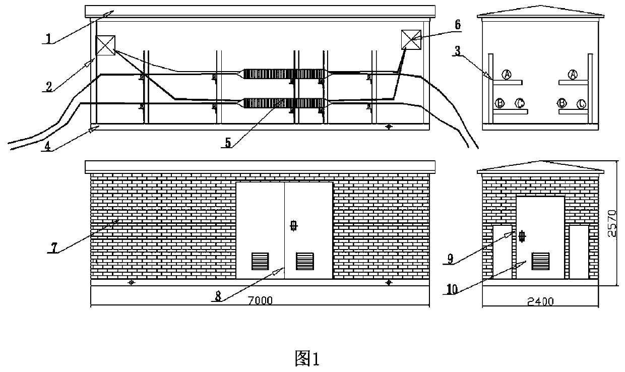
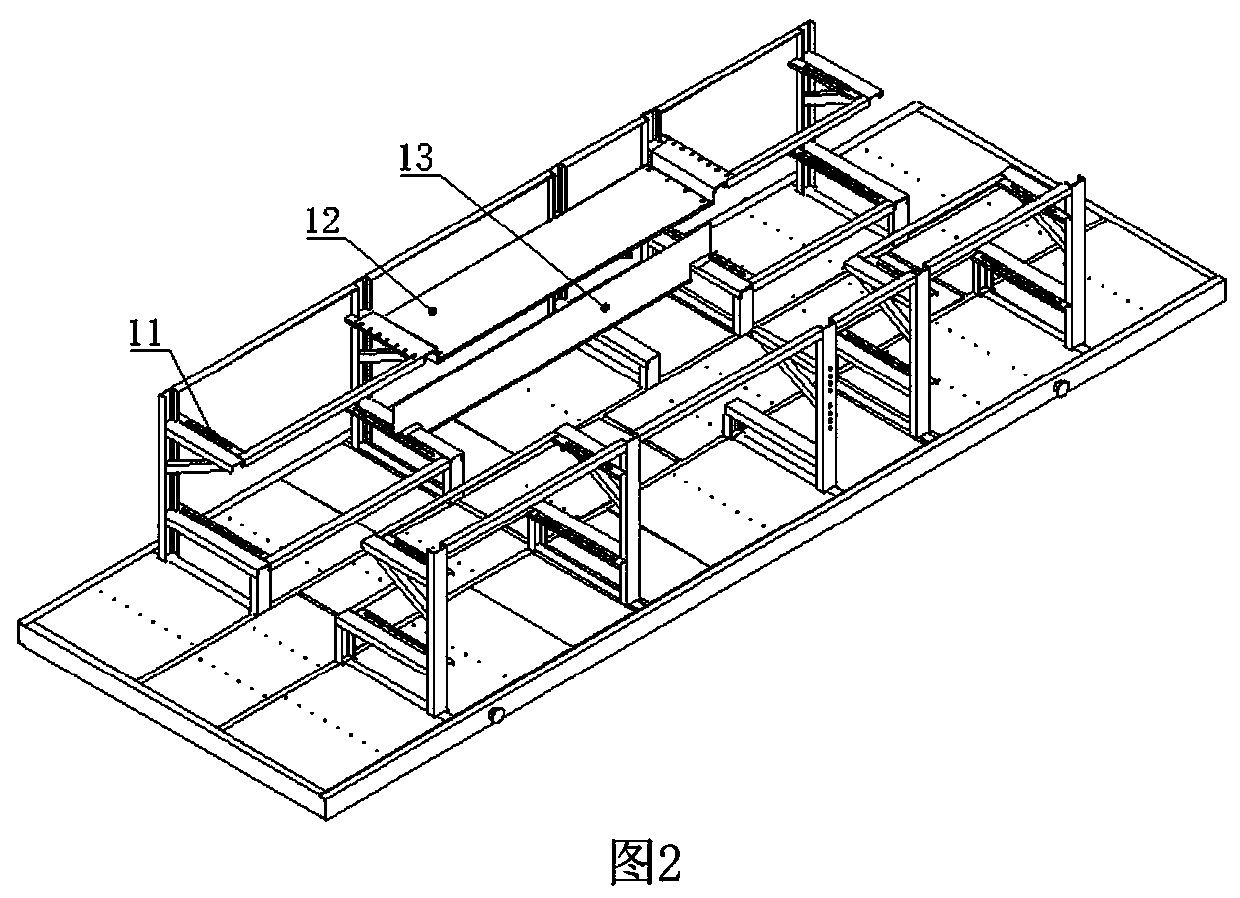
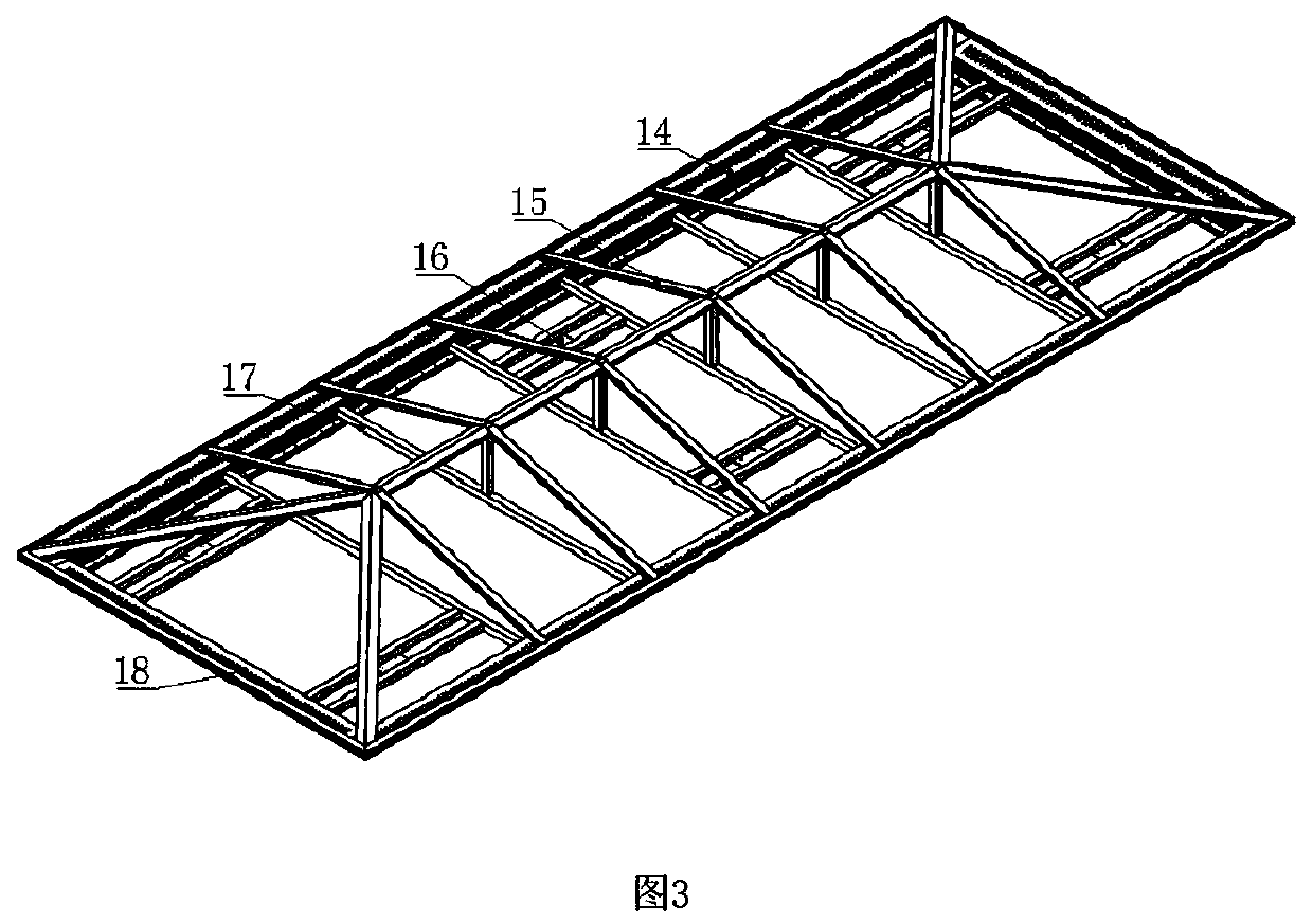
[0014] The technical solutions of the present invention will be clearly and completely described below with reference to the accompanying drawings. A cable joint connection branch box, comprising a box top cover 1, a box frame 2, a cable joint bracket 3, a skid-mounted chassis 4, a high-voltage cable joint 5, a grounding protection box 6, a decorative composite board 7, an access door 8, a high-voltage Cable inlet 9, access door 10, the box top cover 1, box frame 2, cable joint bracket 3, skid-mounted chassis 4 are welded with galvanized profiles, and box top cover 1 is located at the top of the branch box , the cable joint bracket 3 is fixed on the skid-mounted chassis 4, and the box frame 2 is located between the box top cover 1 and the skid-mounted chassis 4; the grounding protection box 6 is fixed inside the box frame 2 with bolts, and the The access door 8 and the access door 10 are fixed on the box frame 2 through stainless steel hinges, and the access door 8 and the access door 10 are provided with rain-proof ventilation shutters; the cable joint bracket 3 and the skid-mounted chassis 4 are welded by welding Forming and fixing, wherein the cable joint bracket 3 is divided into two layers, one phase of the three-phase cable is on the upper layer, and the second phase is on the lower layer, the upper insulation partition 12 is laid under the cable joint of the upper bracket, and the lower insulation is laid between the two cable joints of the lower bracket The partition 13 has cable fixing beams 11 on the upper and lower layers of the cable joint bracket 3 .
[0015] The box top cover 1 includes a top cover ventilation long beam 14, a top plate support beam 15, a cable hoisting fixture 16, a reinforcing square pipe 17, a top cover ventilation side beam 18, a top cover ventilation long beam 14 and a top cover ventilation side. The beam 18 is fixedly connected, and there is a ventilation hole between the two. The cable hoisting fixing frame 16 is between the reinforcing square pipe 17 and the top cover ventilation side beam 18, and a ring-shaped lifting ring is welded. The reinforcing square pipe 17 is located in the top cover ventilation long Between the beams 14 , the roof support frame 15 is above the reinforcing square tube 17 , and the roof support beam 15 is fixed to the roof ventilation long beam 14 .
[0016] The galvanized profiles include galvanized channel steel, galvanized angle steel, and galvanized square pipe.
[0017] The decorative composite board 7 is outside the branch box, riveted and decorated, and the decorative composite board 7 is a polyurethane carved composite board.
[0018] The horizontal height of the support beam supporting the cable head in the cable joint bracket 3 can be adjusted by bolts.
[0019] During the construction operation, the high-voltage cable extends from the ground and enters the cable joint box through the high-voltage cable inlet 9. Because the weight of the high-voltage cable is too heavy, the cable can be lifted by the auxiliary tool (chain hoist) using the cable hoisting bracket 16 on the top cover 1 of the box, and the cable can be placed in the shape of "product" under the condition that the bending radius of the cable is satisfied. on the cable gland bracket 3.
[0020] After the cables to be connected are connected to the branch box from both sides, the cable joint construction can be carried out inside the box. After completing the cable joint, adjust the support height of the movable support beam of the cable joint bracket 3 and fix it with bolts. After the construction is completed, put the upper insulating spacer 12 and the lower insulating spacer 13 into the space and fix them with bolts. Connect the coaxial cable in the cable to the ground protection box 6
[0021] After that, fix the cable on the cable fixing beam 11 with the matching cable fixing clamp. Use an insulating plate to seal the high-voltage cable inlet 9 and fix it with bolts. In this way, the entire high-voltage cable joint is placed on the ground, the maintenance door 8 and the access door 10 are convenient for inspection and maintenance, and the construction in the box is safe and convenient. It can be seen that the invention and utilization of the branch box used for the connection of cable joints of 110kV and above can completely solve many problems such as water soaking, isolation protection, and maintenance of the cable heads in the high-voltage cable joint wells. To ensure the personal safety of construction personnel, ensure the normal operation of cable joints, and ensure the normal operation of the transmission network.

PUM

no PUM

Description & Claims & Application Information

We can also present the details of the Description, Claims and Application information to help users get a comprehensive understanding of the technical details of the patent, such as background art, summary of invention, brief description of drawings, description of embodiments, and other original content. On the other hand, users can also determine the specific scope of protection of the technology through the list of claims; as well as understand the changes in the life cycle of the technology with the presentation of the patent timeline. Login to view more.

Similar technology patents

Counterweight support and motor applying the support

Owner:江阴市澳盛动力设备有限公司

Multicolor integrated dental repair material and preparation method thereof

ActiveCN108578251AGood simulationnice appearance
Owner:上海沪亮生物医药科技有限公司

Hydraulic system of single face machine

ActiveCN102166836Anice appearanceEasy to manufacture and install
Owner:山东力弘智能装备有限公司

Inner pot suitable for electromagnetic heating, manufacturing method of inner pot, and cooking utensil

PendingCN109393987Anice appearanceclear boundaries
Owner:FOSHAN SHUNDE MIDEA ELECTRICAL HEATING APPLIANCES MFG CO LTD

Classification and recommendation of technical efficacy words

Why Eureka
Try Eureka