A speed-regulating power generation device and a speed-regulating method thereof

A power generation device and speed regulation technology, which is applied in the direction of electromechanical devices, electric components, electrical components, etc., can solve problems such as large output power frequency waves and voltage fluctuations, excessive starting and speed-up torque, and generator set speed fluctuations, etc., to achieve Effects of reducing shock, increasing service life, and improving power generation efficiency

Active Publication Date: 2021-07-27
黄明实
View PDF8 Cites 0 Cited by
  • Summary
  • Abstract
  • Description
  • Claims
  • Application Information

AI Technical Summary

Problems solved by technology

A general generator set is composed of a power unit (mostly a three-phase motor, diesel engine or gasoline engine), a generator set and a power distribution control device. After success, the power unit will start the generator set stably and continuously, so as to continuously supply electric energy to the outside, that is, the mechanical energy (kinetic energy) of the power unit will be converted into electrical energy through the generator; since the power unit and the generator set are started at the same time, the generator set will The mass inertia of its own is relatively large, and the start is relatively slow. The torque will be too large during the start-up and speed-up process of the generator set. When the power unit speeds up the generator set, it is limited by the driving force; However, the optimal speed of the power unit is not exactly the same as the speed of the generator set, which makes the speed of the generator set fluctuate greatly, and the frequency wave and voltage fluctuation of the output power are relatively large.
However, at present, there is no speed regulating device that can timely and reliably adjust the speed of the generator set, so that the generator can respond in time, so as to reduce the impact damage of the power unit and the generator set, and the speed regulation accuracy is poor and the cost is high.

Method used


Image

  • A speed-regulating power generation device and a speed-regulating method thereof
  • A speed-regulating power generation device and a speed-regulating method thereof

Examples


Embodiment Construction

[0022] In order to make the purpose, technical solution and advantages of the invention clearer, the invention will be further described in detail below with reference to the drawings and preferred embodiments. However, it should be noted that many of the details listed in the specification are merely for the reader to have a thorough understanding of one or more aspects of the invention, and these aspects of the invention can be practiced without these specific details.

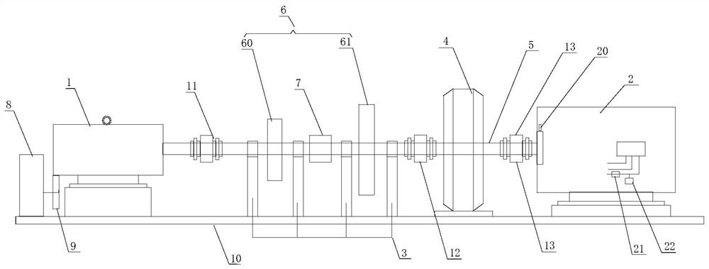
[0023] Such as figure 1 As shown, a speed-regulating power generation device according to the invention includes a support base 10 and a power motor 1 installed on the support base 1, a generator 2, a bearing seat 3, a transmission 4 and a clutch 7, and the power motor 1 Between the output shaft and the input shaft of the generator 2, there are multiple transmission shafts 5 arranged in a coaxial transmission connection, and each transmission shaft 5 is supported and installed on the support base 10 by sever...


PUM


Abstract

The invention discloses a power generation speed regulating device and a speed regulating method thereof, comprising a support base and a power motor installed on the support base, a generator, a bearing seat, a transmission and a clutch, and multiple stages are arranged between the power motor and the generator The transmission shafts are coaxially connected. Each section of the transmission shaft is supported and installed on the support base by several bearing seats arranged at intervals. Each section of the transmission shaft is connected in series by a plurality of flywheels with different diameters. A clutch is arranged on the transmission shaft between them, the power motor is connected with the transmission shaft through the first coupling, and a transmission is arranged on the tail end close to the transmission shaft, and the transmission shaft between the transmission and the generator passes through the first Three-coupling drive connection. The invention can effectively change the load when the power motor is started and quickly adjust the rotating speed of the generator, so that the power motor can be started quickly under light load conditions, effectively improves the speed-up effect, and reduces the impact on the power motor.

Description

technical field [0001] The invention belongs to the technical field of generators, and in particular relates to a power generation speed regulating device and a speed regulating method thereof. Background technique [0002] Power generation is widely used in places where the power grid cannot cover, and for emergency backup power; with the advancement of technology, as a high-quality choice of emergency power for production purposes, lightweight and portable small generator sets have also begun to enter the daily life of industrial enterprises. in production. The power generator is generally a system composed of a starter motor, a generator and other auxiliary parts, generally called a generator set. A general generator set is composed of a power unit (mostly a three-phase motor, diesel engine or gasoline engine), a generator set and a power distribution control device. After success, the power unit will start the generator set stably and continuously, so as to continuousl...

Claims


Application Information

Patent Timeline
Patent Type & Authority Patents(China)
IPC IPC(8): H02K7/18H02K7/116H02K7/11H02K7/02H02K11/21H02K11/26H02K11/27H02K11/30
CPCH02K7/025H02K7/11H02K7/116H02K7/1846H02K11/21H02K11/26H02K11/27H02K11/30Y02E60/16
Inventor 黄明实莫增吉覃瑞长廖文锐黄立产
Owner 黄明实
Why Eureka
Try Eureka