Sheet metal welding fixture

A welding fixture and sheet metal technology, applied in the field of sheet metal welding fixtures, can solve the problems of increased time cost, labor cost, increased economic cost of sheet metal parts, and waste of time, so as to reduce labor cost and economic cost , Adjust the effect of convenience

Inactive Publication Date: 2020-07-24
ZHENGZHOU UNIV OF IND TECH
View PDF9 Cites 0 Cited by
  • Summary
  • Abstract
  • Description
  • Claims
  • Application Information

AI Technical Summary

Problems solved by technology

Although the single structure of the fixture is simple, in actual use, it needs multiple groups to be used together to realize the overall positioning of the entire sheet metal part. The shape of the parts needs to be adjusted one by one. The adjustment is c

Method used


Image

  • Sheet metal welding fixture
  • Sheet metal welding fixture
  • Sheet metal welding fixture

Examples


Embodiment 1

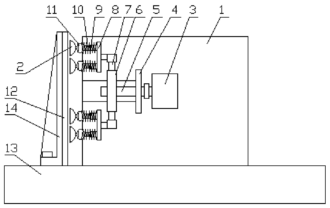
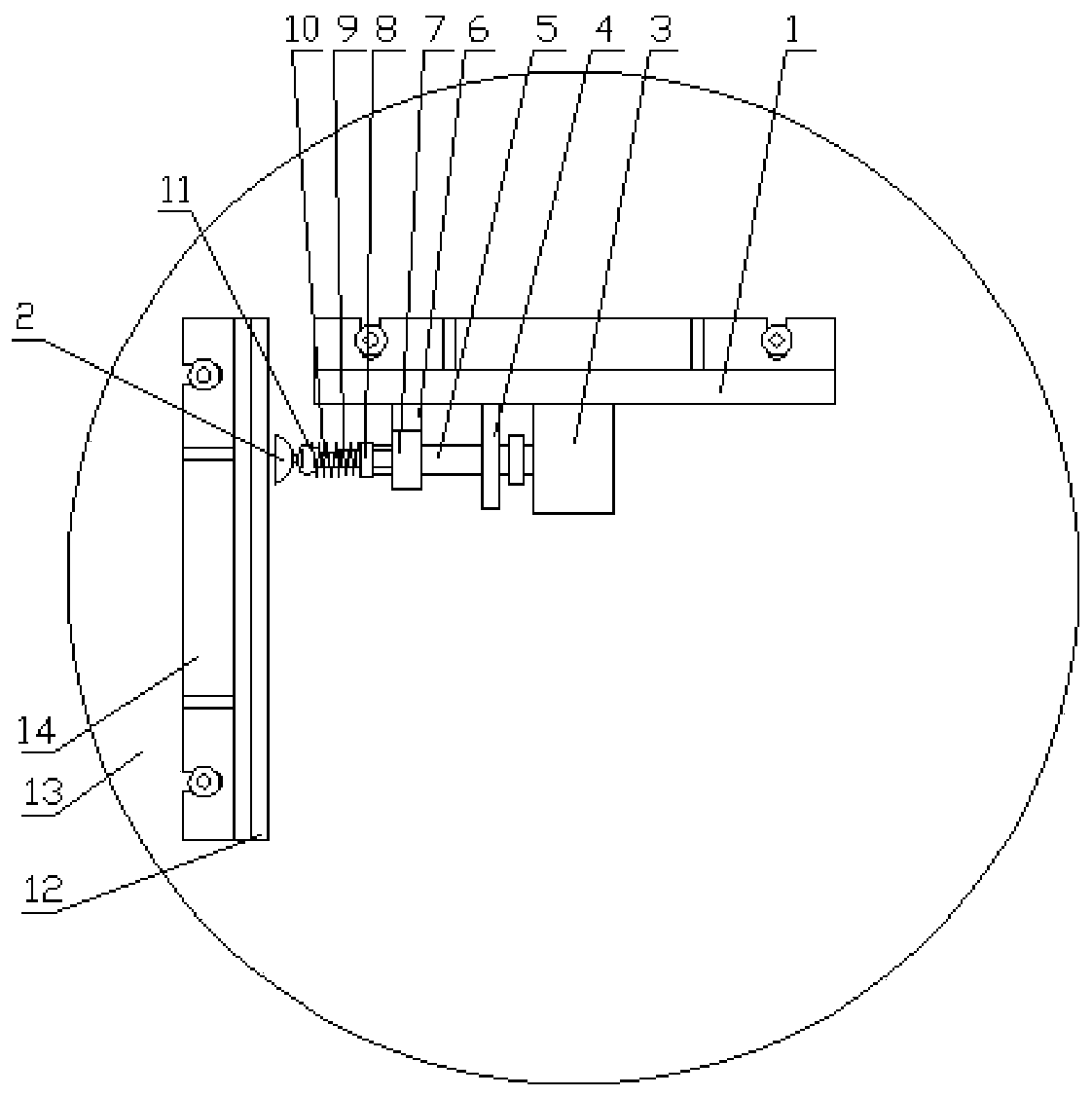
[0034] Such as figure 1 and figure 2 As shown, a kind of sheet metal welding fixture provided by the present invention comprises:

[0035] Workbench 13 used as integral support;

[0036] Bending plate 14 is pressed on the table top of the workbench 13 by a pressing plate or a T-bolt;

[0037] Bending plate two 1 is pressed on the table top of the workbench 13 by a pressing plate or a T-bolt, and the working surface of bending plate two 1 is perpendicular to the working surface of bending plate one 14;

[0038] The support 4 is connected to the working surface of the bent plate 2 1 by bolts;

[0039] The motor 3 is connected to the working surface of the bent plate 1 by bolts, and the output shaft of the motor 3 is arranged on the side close to the bent plate 14;

[0040] Screw 5, one end of which is connected to the output shaft of motor 3 through a coupling, and the other end is erected on the support 4 through a bearing;

[0041] The nut seat 6 is arranged on the end o...

Embodiment 2

[0049] In order to further expand the scope of application of the clamp, telescopic rods 7 for extending the range of action of the clamp are respectively provided at both ends of the nut seat 6, and the setting of the two telescopic rods makes the range of action of the pressure block 2 larger.

[0050] One end of the telescopic rod 7 away from the nut seat 6 is fixedly connected to the strut, the center line of the strut is perpendicular to the center line of the telescopic rod 7, and the end of the strut away from the telescopic rod 7 is vertically fixed to the plate body 8, and the plate body 8 is provided with at least one Rod body 10.

[0051] Further, the telescopic rod 7 includes a sleeve 2 and an inner rod body 2, one end of the sleeve 2 is fixed to the nut seat 6, one end of the inner rod body 2 is inserted into the sleeve 2, and the other end is fixed to the strut, A fastening screw for fastening the position of the inner rod body two is arranged on the sleeve two. ...

Embodiment 3

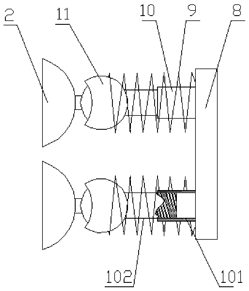
[0054] In order to further adapt to the shape changes of sheet metal parts, such as image 3 As shown, the rod body 10 is set to a structure whose length can be adjusted adaptively. The specific structure is that the rod body 10 includes a sleeve one 101 and an inner rod body one 102, one end of the sleeve one 101 is vertically fixed to the plate body 8, and the inner rod body One end of one 102 is inserted into the sleeve one 101, the other end is fixed with the ball head housing 11, and the sleeve one 101 is covered with a spring 9, one end of the spring 9 is in contact with the plate body 8, and the other end is connected with the ball head housing 11 butt.

[0055] The spring 9 is preferably a hard spring, which can not only meet the needs of clamping, but also adapt to changes in the shape of the sheet metal within a certain range.

[0056] In use, the plug-in structure of the inner rod body 102 and the sleeve 101 enables the coincidence of the two to be adjusted to a ce...


PUM


Abstract

The invention relates to a sheet metal welding fixture. The sheet metal welding fixture comprises a workbench; a bending plate I arranged on the workbench; a bending plate II arranged on the workbenchwith the working surface vertical to the working surface of the bending plate I; a motor arranged on the working surface of the bending plate II; a screw with one end connected with an output shaft of the motor and the other end erected on a support; a nut seat which is arranged at one end of the screw away from the motor, and is clamped in a sliding groove horizontally arranged on the working surface of the bending plate II and can move along the length direction of the sliding groove; even number of rod bodies, which are symmetrically arranged at the two ends of the nut seat, and the centerline thereof is parallel to the center line of the screw; a ball head shell arranged at one end of the rod bodies away from the nut seat; a ball head screw, the ball head end of which is inserted inthe ball head shell; and a pressing block detachably connected to one end of the ball head screw away from the ball head shell. According to the sheet metal welding fixture provided by the invention,the structure is reasonable, the overall clamping stability is good, the disassembly and assembly are simple, the adjustment is convenient, and the total economic cost of workpieces is reduced.

Description

technical field [0001] The invention belongs to the technical field of auxiliary processing equipment for welding, and in particular relates to a sheet metal welding fixture. Background technique [0002] In the sheet metal processing process, welding is a very important process. In order to stabilize the position of the sheet metal parts during sheet metal welding, it is often achieved by means of fixtures. For example, a patent document with application number CN201921496696.6 provides a A fixture for sheet metal welding. Its structure includes a console. The upper surface of the console is provided with a fixed base and a slide rail. The fixed base is located on one side of the slide rail. The outer surface of the slide rail is provided with a movable base. The setting of the rail, the slide rail can make the fixture slide, and can be used for workpieces of various sizes, and can be fixed for it. Through the setting of the lifting rod, the lifting rod can raise and lower ...

Claims


Application Information

Patent Timeline
IPC IPC(8): B23K37/04
CPCB23K37/0443
Inventor 牛瑞利曲全鹏
Owner ZHENGZHOU UNIV OF IND TECH
Why Eureka
Try Eureka