Industrial gas pipeline welding device

A technology of industrial gas and welding equipment, applied in auxiliary equipment, welding equipment, auxiliary welding equipment and other directions, can solve the problems of danger and poor welding effect, and achieve the advantages of welding, welding accuracy, and better and labor-saving feeding process. Effect

Inactive Publication Date: 2020-07-24
赵艳
View PDF5 Cites 3 Cited by
  • Summary
  • Abstract
  • Description
  • Claims
  • Application Information

AI Technical Summary

Problems solved by technology

[0003] At present, in the process of producing industrial gas pipelines, it is usually necessary to weld two processed gas pipelines together, but the existing welding devices still have certain deficiencies. There are certain limitations in the use of fixed welding of gas pipelines, and during the welding process, the welding position at the bottom requires the staff to lower their heads to weld, which not only has certain dangers, but also has poor welding effect. Therefore, it is urgent to design a Industrial gas pipeline welding device to solve the above problems

Method used


Image

  • Industrial gas pipeline welding device
  • Industrial gas pipeline welding device
  • Industrial gas pipeline welding device

Examples


Embodiment 1

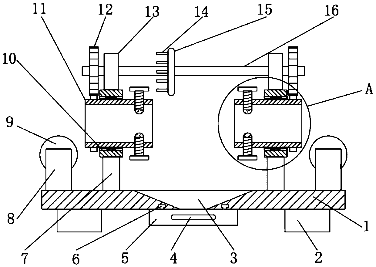
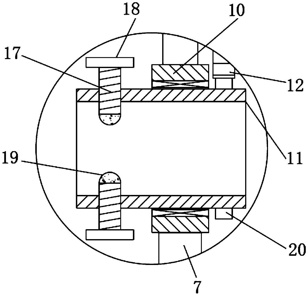
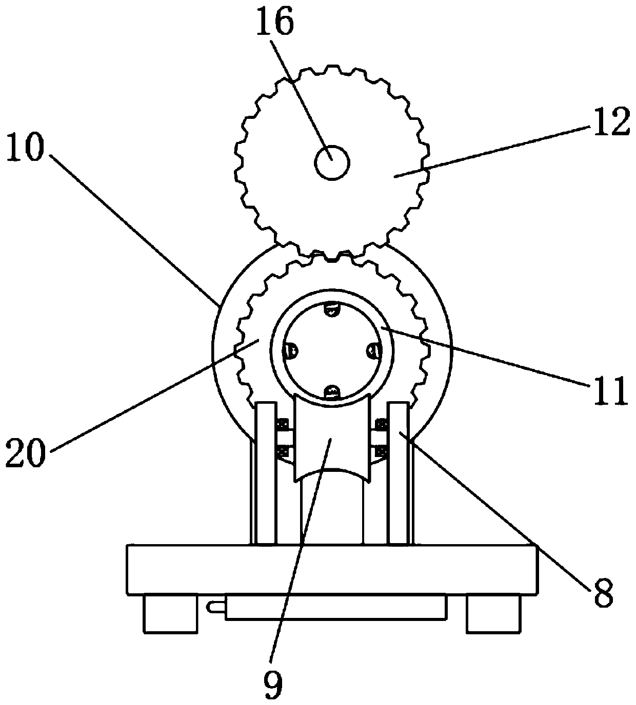
[0032] refer to Figure 1-4 , an industrial gas pipeline welding device, including a base plate 1, a cylinder 10 and a fixed cylinder 11, support blocks 2 are evenly welded at the four corners of the bottom outer wall of the base plate 1, and upright columns are welded on the top outer wall of the base plate 1 near both sides 7, and the top outer wall of the column 7 is welded to the bottom outer wall of the cylinder 10, the inner wall of the cylinder 10 and the outer wall of the fixed cylinder 11 are rotatably connected by bearings, and the outer wall of the fixed cylinder 11 is provided with threaded holes that are equidistant and annularly distributed, and The inner wall of the threaded hole is threadedly connected with a stud 17, the top of the stud 17 is welded with an adjustment wheel 18, the top outer wall of the fixed cylinder 11 is welded with a riser 13, and one side outer wall of the riser 13 has a concave hole, the concave hole The inner wall is rotatably connected...

Embodiment 2

[0036] refer to Figure 5 , an industrial gas pipeline welding device. Compared with Embodiment 1, this embodiment also includes a fixed rod 21 welded on the top outer wall of the bottom plate 1, and a shaped hose 22 is welded on the top outer wall of the fixed rod 21. The shaped hose 22 A goggle is welded on the outer wall of one end of the goggle, and one side of the goggle is provided with an installation opening, and the inner wall of the installation opening is connected with goggles 23 by fastening bolts.

[0037] Working principle: During the welding process, the shape of the shaped hose 22 can be changed at will, so that the goggles 23 on the shaped hose 22 can be placed in front of the worker, which protects the eyes and effectively improves the safety performance of the device during use .


PUM


Abstract

The invention discloses an industrial gas pipeline welding device. The industrial gas pipeline welding device comprises a bottom plate, a barrel and a fixed barrel. Supporting blocks are evenly weldedto the four corners of the outer wall of the bottom of the bottom plate, and stand columns are welded to the positions, close to the two sides, of the outer wall of the top of the bottom plate, and the outer walls of the tops of the stand columns and the outer wall of the bottom of the barrel are welded. The inner wall of the barrel and the outer wall of the fixed barrel are rotationally connected through a bearing. Threaded holes annularly distributed at equal intervals are formed in the outer wall of the fixed barrel, and the inner walls of the threaded holes are in threaded connection withdouble-screw bolts. Adjusting wheels are welded to the tops of the double-screw bolts. According to the industrial gas pipeline welding device, a gas pipeline can roll in an arc-shaped grove in a roller and can be directly conveyed into the fixed barrel, so that more labor is saved in the feeding process, and the use effect is better; gas pipelines of different sizes can be fixed and welded, useis more flexible, weld joints of the gas pipelines can be rotated to face workers, observation is convenient, and the industrial gas pipeline welding device is more beneficial to welding, and weldingis more precise.

Description

technical field [0001] The invention relates to the technical field of gas pipeline processing, in particular to an industrial gas pipeline welding device. Background technique [0002] Gas pipelines are pipelines that transport natural gas, including associated gas produced in oil fields, from mining sites or processing plants to urban gas distribution centers or industrial enterprise users. They are also called gas pipelines. Natural gas pipelines are used to transport natural gas. Natural gas pipelines account for about half of the total length of pipelines in the world, and the gas pipelines used for industrial production and the gas pipelines used for transportation are the same. [0003] At present, in the process of producing industrial gas pipelines, it is usually necessary to weld two processed gas pipelines together, but the existing welding devices still have certain deficiencies. There are certain limitations in the use of fixed welding of gas pipelines, and dur...

Claims


Application Information

Patent Timeline
Patent Type & Authority Applications(China)
IPC IPC(8): B23K37/053B23K37/00B23K101/06
CPCB23K37/00B23K37/0533B23K37/0538B23K2101/06
Inventor 赵艳
Owner 赵艳
Why Eureka
Try Eureka