Gas conveying equipment for metallurgical machinery

A technology of conveying equipment and gas conveyor, which is applied in the direction of mechanical equipment, gas/liquid distribution and storage, non-detachable pipe connection, etc., and can solve the hidden dangers of equipment aging, valve body corrosion and perforation, suction and exhaust at pipe body connections and other issues, to achieve the effect of strengthening the sealing, strengthening the fastening, and avoiding large-scale explosion and combustion

Inactive Publication Date: 2020-07-24
吴锦丁
View PDF0 Cites 0 Cited by
  • Summary
  • Abstract
  • Description
  • Claims
  • Application Information

AI Technical Summary

Problems solved by technology

[0004] The main purpose of the present invention is to overcome the deficiencies of the prior art and provide a gas conveying equipment for metallurgical machinery to solve the problems of gas explosions in industrial production, local corrosion and perforation of the a...

Method used


Image

  • Gas conveying equipment for metallurgical machinery
  • Gas conveying equipment for metallurgical machinery
  • Gas conveying equipment for metallurgical machinery

Examples


Embodiment 1

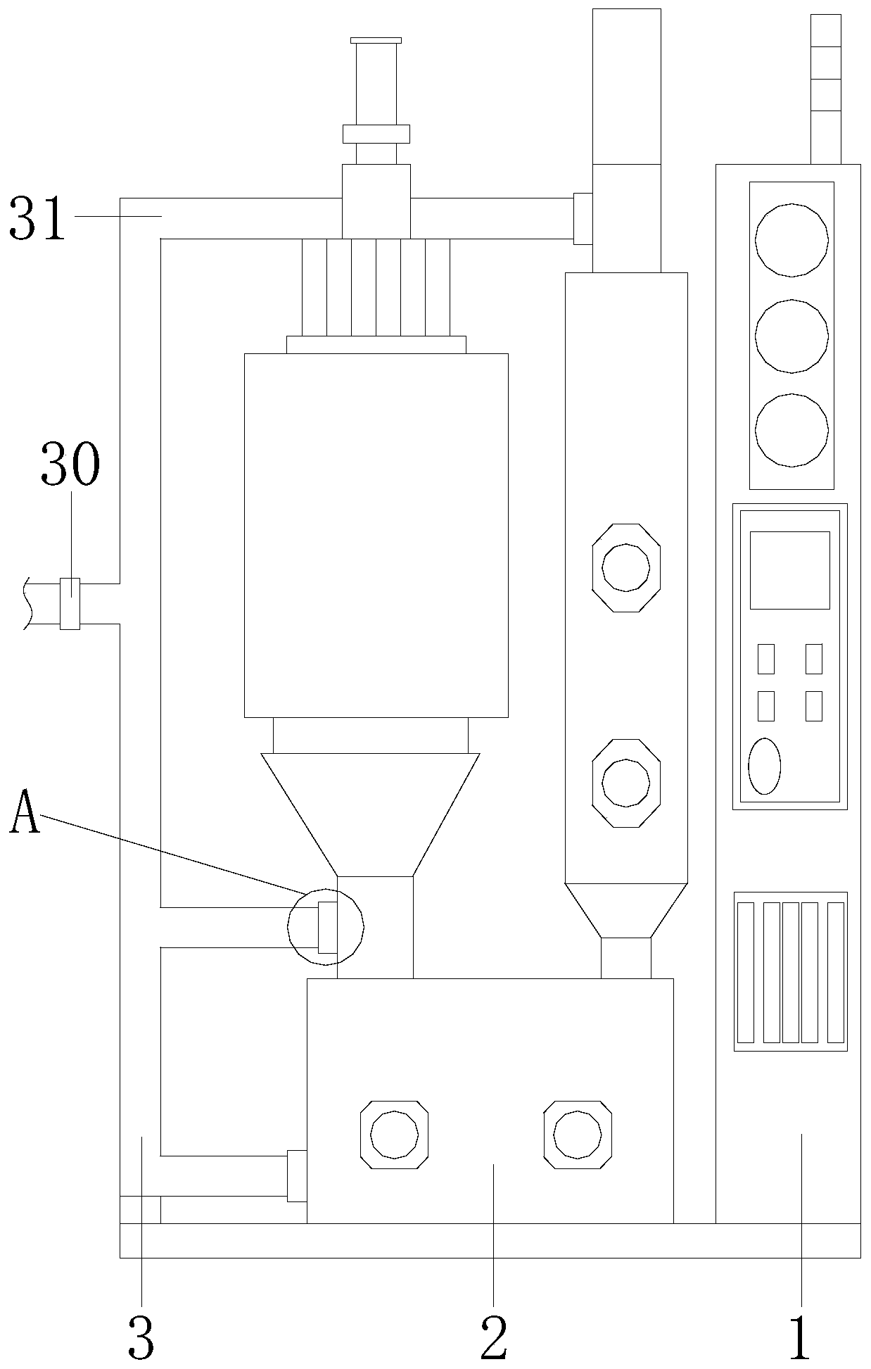
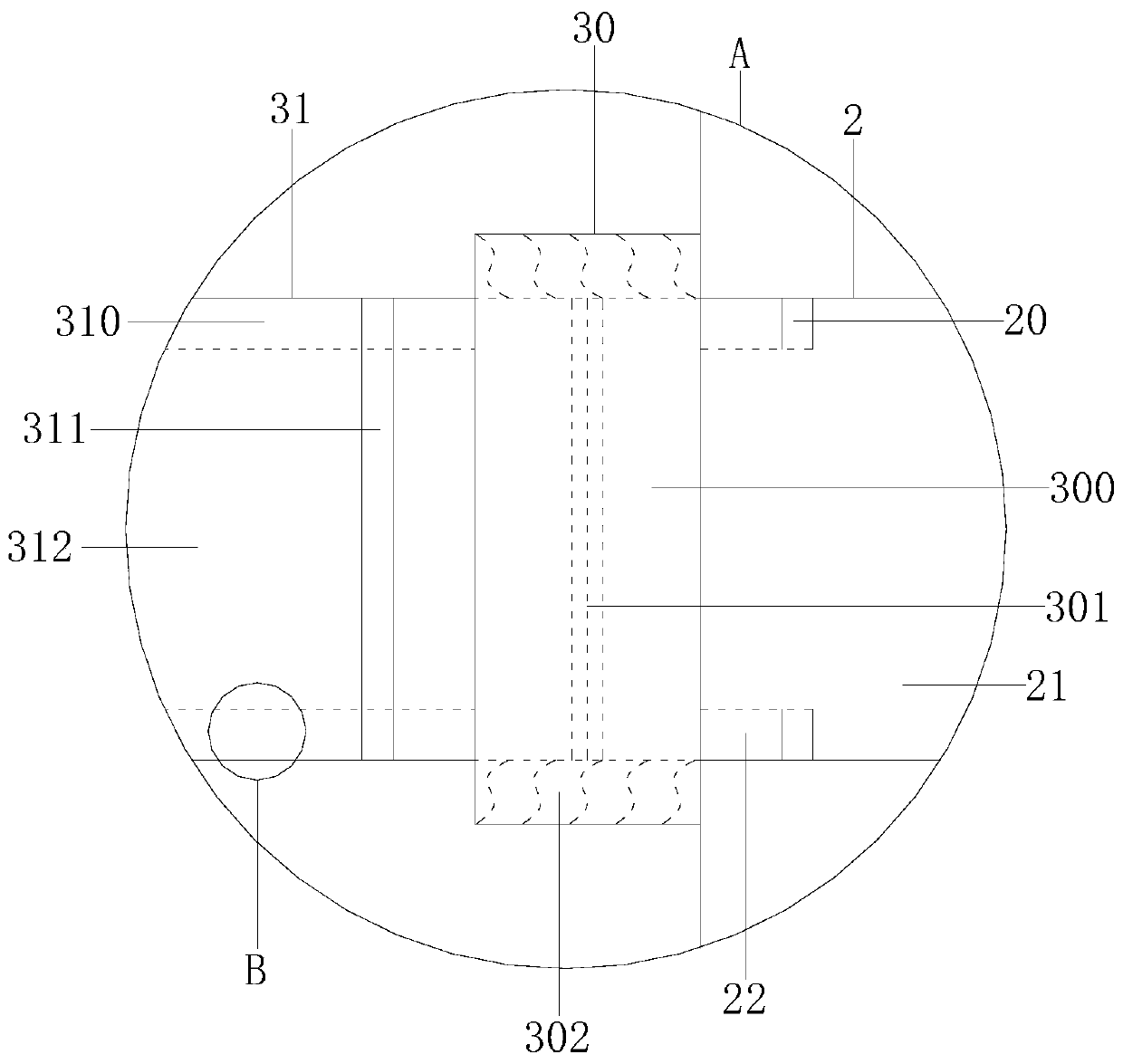
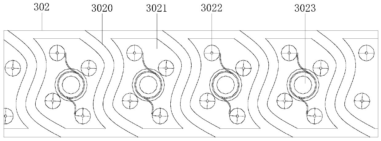
[0026] see Figure 1-4 , the present invention provides a technical solution for gas conveying equipment for metallurgical machinery: its structure includes a console 1, a gas conveying machine 2, and a gas conveying pipe 3, the console 1 is locked with the gas conveying machine 2 and the two are electrically connected, The gas conveyor 2 is installed and connected to the gas delivery pipe 3. The gas conveyor 2 is composed of a gas storage fastener 20, a gas storage machine 21, and a gas storage limit groove 22. The gas storage fastener 20 is installed On the gas storage machine 21, the gas storage fastener 20 is equipped with a gas storage limit groove 22, and the gas delivery pipe 3 includes a pipeline swivel 30 and a pipeline 31, and the pipeline swivel 30 is embedded with the pipeline 31. The pipe swivel 30 is fitted with the pipe 31, and the thread design strengthens the fastness of the two. The pipe swivel 30 includes a swivel 300, a swivel groove 301, and a helical stru...

Embodiment 2

[0029] see Figure 5-6, the present invention provides a technical solution for gas conveying equipment for metallurgical machinery: the pipe side device 310 in its structure includes a support rod 3100, a stacking device 3101, an upper plate 3102, a middle plate 3103, a bottom plate 3104, and a main steel layer 3105, the tube layer of the tube side device 310 is relatively thick, and the multi-layer steel layer is protected when hammering, the support rod 3100 is installed and connected with the upper plate 3102, the middle plate 3103, and the bottom plate 3104, and the stacker 3101 Installed on the middle plate 3103, the stacker 3101 not only plays the role of driving but also plays the role of support and reinforcement, the bottom plate 3104 is welded with the main steel layer 3105, and the stacker 3101 includes a transmission stack Rod 500, fitting swivel 501, fastening groove 502, fitting plate 503, transmission round shaft 504, described transmission stacking rod 500 is ...


PUM


Abstract

The invention discloses gas conveying equipment for metallurgical machinery. The gas conveying equipment structurally comprises a control panel, a gas conveyor and a gas conveying pipe, wherein the control panel and the gas conveyor are locked and electrically connected; the gas conveyor and the gas conveying pipe are installed and connected; the gas conveyor comprises gas storage fasteners, a gasstorage machine and gas storage limit slots, and the gas storage fasteners are arranged on the gas storage machine; a pipeline spiral ring and a pipeline are embedded, and the tightness of the pipeline spiral ring and the pipeline is strengthened through the thread design; melt glue blocks are filled between the pipeline spiral ring and the pipeline, so that the sealing property is enhanced, andonce the fatigue break occurs at a joint, the pipeline connected to a gas blow-out position is hammered by a tool and the pipeline spiral ring, the pipeline and the gas conveyor are further embedded and reinforced; and the melt glue blocks flow in a connecting port of the pipeline spiral ring and the pipeline when the melt glue blocks are melted, the pipeline gas no longer flows, the gas discharging amount is controlled in time, and the occurrence of large-scale explosion combustion is avoided.

Description

technical field [0001] The invention relates to the field of metallurgical machinery, in particular to gas conveying equipment for metallurgical machinery. Background technique [0002] Gas conveying equipment is widely used in industrial production. Metallurgical processing usually needs to consume a large amount of gas for heating. The conveying process has a greater fire risk. It is very important to strengthen the fire safety of combustible gas conveying. [0003] In the prior art, many gas explosion incidents have occurred in industrial production. The aging valve body of the equipment is partially corroded and perforated, and the gas is sucked and exhausted through the joint of the pipe body to form a hidden danger. Once the joint is fatigued and broken, high-pressure flammable gas will be ejected and cause large-scale explosion and combustion. . Contents of the invention [0004] The main purpose of the present invention is to overcome the deficiencies of the prior...

Claims


Application Information

Patent Timeline
IPC IPC(8): F16L15/04F16L13/11F17D1/065
CPCF16L13/11F16L15/04F17D1/065
Inventor 吴锦丁
Owner 吴锦丁
Why Eureka
Try Eureka