
Thin film magnetic sensor with groove structure

A magnetic sensor and thin film technology, applied in the field of sensors, can solve the problems of size and change degree limitation, adjustment of particle type or content of each component, reduction of sensitivity of magnetic film, etc., to achieve the effect of improving sensitivity

Inactive Publication Date: 2021-09-07
SHANGHAI JIAO TONG UNIV
View PDF5 Cites 0 Cited by
  • Summary
  • Abstract
  • Description
  • Claims
  • Application Information

AI Technical Summary

Problems solved by technology

Therefore, according to formula (3), even if the magnetic permeability μ of the magnetic material itself r Very large, when it is made into a sample of a specific shape (such as a film shape), the demagnetization field H d will also make the actual permeability μ of the sample eff The size and degree of change are limited, and the maximum change range is only 1 / N d
This greatly reduces the sensitivity of the magnetic film to external magnetic fields, which in turn reduces the sensitivity of the sensor
Demagnetizing field H d The size of the magnetic film is closely related to the shape and structure of the magnetic film. The traditional improvement method is to change the microscopic composition of the soft magnetic material selected for the magnetic film or to reduce the size of the magnetic film by changing the size of the magnetic film (such as increasing the aspect ratio, reducing the overall thickness, etc.) Small demagnetizing field H d However, under the premise of a given soft magnetic material, it is impossible to adjust the particle type or the content of each component selected by the material, but relying on adjusting the external size of the film, although the demagnetization factor N can be reduced d , to increase the effective permeability μ of the film eff , but this change in the overall size will affect the inductance value of the thin film coil, and ultimately affect the sensitivity performance of the sensor

Method used


Image

  • Thin film magnetic sensor with groove structure
  • Thin film magnetic sensor with groove structure
  • Thin film magnetic sensor with groove structure

Examples


Embodiment

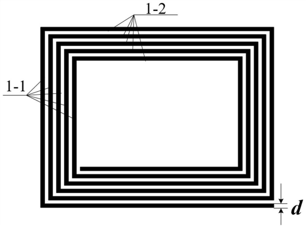
[0045] Such as image 3 Schematic diagram of the structure of the rectangular spiral coil;

[0046] The rectangular spiral coil 1 has a rectangular planar spiral structure as a whole, and the wires in the two vertical directions are composed of a conductor, and the width of each conductor is d;

[0047] The corners of the rectangular spiral coil 1 are vertically connected by a conductor 1 - 2 parallel to the long side direction of the magnetic film 2 and a conductor 1 - 1 in the short side direction.

[0048] The conductors constituting the rectangular spiral coil 1 are divided into two parts: a conductor 1-1 parallel to the short-side direction of the magnetic film 2 and a conductor 1-2 in the long-side direction. If the magnetic field to be measured is applied along the direction of the long side of the magnetic film 2, the conductor 1-1 perpendicular to the direction of the magnetic field to be measured on the coil 1 can cause a sensing response in the direction of the lon...


PUM


Abstract

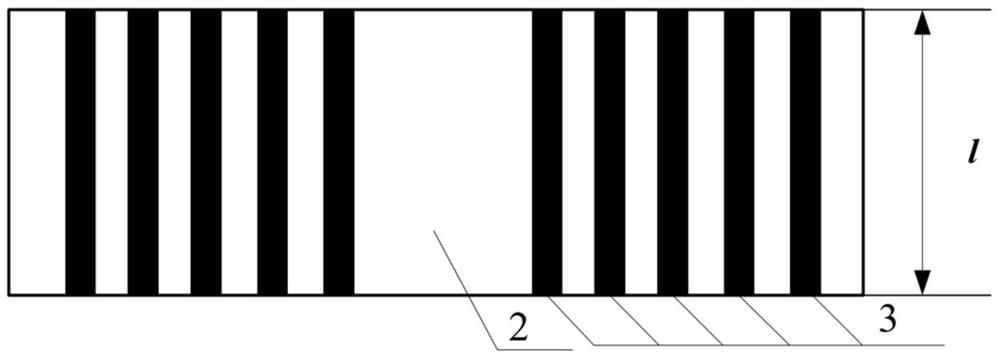
A thin-film magnetic sensor with a groove structure is characterized in that a rectangular spiral coil is arranged between two layers of rectangular magnetic films, and the rectangular spiral coil is a planar spiral structure as a whole; the rectangular spiral coil Spiral out clockwise or counterclockwise from a certain position inside the rectangle; the inner surfaces of the two layers of rectangular magnetic films have multiple groups perpendicular to their sensing direction (that is, the direction of the magnetic field to be measured, usually the film length direction) Rectangular grooves, the number of groups of the rectangular grooves is equal to the number of turns of the rectangular spiral coil; the rectangular grooves of the two layers of rectangular magnetic films are opposite, and the rectangular spiral coils are connected to A conductor perpendicular to the sensing direction is embedded in the rectangular magnetic film. The invention effectively improves the sensitivity of the thin film magnetic sensor to the external magnetic field.

Description

technical field [0001] The invention relates to a sensor, especially a thin-film magnetic sensor with a groove structure. Background technique [0002] Magnetic sensors are one of the most widely used sensors, and can directly or indirectly measure many physical, chemical, biological and other parameters through magnetic field measurement. The planar spiral coil and the soft magnetic film made of high magnetic permeability soft magnetic material can be combined to form a magnetic sensor with a thin film coil structure. [0003] The sensing process of the external magnetic field of the thin film magnetic sensor can be divided into two stages: [0004] In the first stage, in the thin film coil, the effective magnetic permeability of the soft magnetic film μ eff External magnetic field H app the response to: [0005] According to the magnetic properties (magnetization curve) of the soft magnetic material, in the process of magnetization, the effective permeability μ of the ...

Claims


Application Information

Patent Timeline
Patent Type & Authority Patents(China)
IPC IPC(8): G01R33/05
CPCG01R33/05
Inventor 文玉梅周效宽李平王遥
Owner SHANGHAI JIAO TONG UNIV
Learn More