
A thin -film fiber partial device

A polarizer and optical fiber technology, applied in optical components, instruments, optics, etc., can solve problems such as large volume and complex structure, and achieve the effect of reducing insertion loss and volume, flexible structure, and simplified structure

Active Publication Date: 2021-04-02
BEIHANG UNIV
View PDF6 Cites 0 Cited by
  • Summary
  • Abstract
  • Description
  • Claims
  • Application Information

AI Technical Summary

Problems solved by technology

[0004] At present, the commonly used optical fiber polarizers, such as birefringent crystal type or polarizer type, have relatively complex structures, need to be bonded with glue, and are relatively large in size

Method used


Image

  • A thin -film fiber partial device
  • A thin -film fiber partial device
  • A thin -film fiber partial device

Examples


Embodiment Construction

[0032] The technical solutions in the embodiments of the present invention will be clearly and completely described below in conjunction with the accompanying drawings in the embodiments of the present invention. Obviously, the described embodiments are only for illustration and are not intended to limit the present invention.

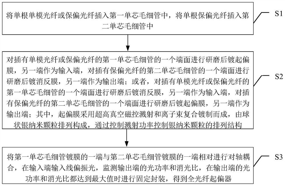
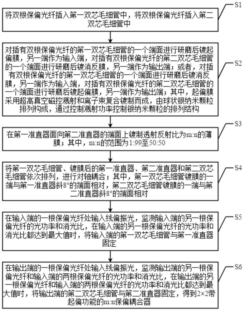
[0033] A kind of manufacturing method of all-optical fiber polarizer provided by the present invention, such as figure 1 shown, including the following steps:

[0034] S1: Insert a single single-mode fiber or polarization-maintaining fiber into the first single-core capillary, and insert a single polarization-maintaining fiber into the second single-core capillary;

[0035] S2: One end face of the first single-core capillary inserted with single-mode optical fiber or polarization-maintaining optical fiber is polished and then coated with polarizing film, and the other end is used as the input end, and one end face of the second single-core capillary in...


PUM


Abstract

The invention discloses a thin film type optical fiber polarizing device, which realizes the polarizing function by means of optical fiber coating. The coated polarizing film is composed of the arrangement of spherical silver nano-particles, the distribution of silver nano-particles has dichroic property, which can realize the polarizing function and replace the birefringent crystal or polarizer in the existing optical fiber polarizer, thus simplifying the structure of the optical fiber polarizer, reducing the insertion loss and volume of the optical fiber polarizer, and reducing the processing cost. Moreover, the polarizing function is realized by means of optical fiber coating, since no additional devices are added, the coated polarizing film is easy to be coupled and integrated with other optical waveguides, has a flexible structure, and can realize multi-functional integrated devices, which is very suitable for the field of optical fiber current sensing and fiber optic gyroscope.

Description

technical field [0001] The invention relates to the technical field of optical fiber sensing, in particular to a film-type optical fiber polarizing device. Background technique [0002] Optical fiber sensing technology is developed along with the development of optical fiber communication technology. It is a new type of sensing technology that uses optical fiber as the medium and light wave as the carrier to sense and transmit the external measured signal. It has the advantages of small size, light weight, high sensitivity, wide frequency range, large dynamic range, anti-electromagnetic interference, corrosion resistance, high pressure resistance, explosion-proof, flame-proof, good flexibility of optical path, easy to realize long-distance measurement, and convenient composition The sensor network and the realization of multi-point measurement are widely used in the fields of national defense and military, aerospace, industrial, mining and agriculture, energy and environment...

Claims


Application Information

Patent Timeline
Patent Type & Authority Patents(China)
IPC IPC(8): G02B6/27
CPCG02B6/2726G02B6/276
Inventor 于佳王夏霄徐宏杰马福
Owner BEIHANG UNIV
Learn More