
Intelligent infusion apparatus capable of automatically replacing infusion container

An automatic replacement and infusion container technology, which is applied in the field of medical devices, can solve the problems of manpower and time consumption, nurses' time and energy, etc., and achieve the effects of drip rate monitoring, wide applicability, and stable clamping of the bottle mouth

Pending Publication Date: 2020-07-28
河北华创志业医疗科技有限公司
View PDF1 Cites 18 Cited by
  • Summary
  • Abstract
  • Description
  • Claims
  • Application Information

AI Technical Summary

Problems solved by technology

[0002] At present, the infusion operations in the hospital wards all use common infusion stands. Although multiple bottles of liquid medicine can be hung on each shelf, the bottles must be changed by a nurse, and the patient or family member needs to be taken care of. Informing the nurse to change the bottle, this process consumes a lot of manpower and time, especially in large hospitals with many wards, the infusion bottle change takes a lot of time and energy for the nurses, for this reason, Chinese patent CN109771731A discloses an automatic patient infusion bottle changer The bottle device includes a fixing seat, grooves distributed equidistantly on the outer wall of the top of the fixing seat, and an infusion bottle is placed on the inner wall of the groove, and a bearing is welded on the inner wall of the bottom of the fixing seat, and the bearing The inner wall of the drive shaft is rotatably connected with a drive shaft, the outer wall of the drive shaft is welded with a driving sprocket, the outer wall of the drive sprocket is connected with a drive chain, and the drive chain is driven on the inner wall of the side away from the drive sprocket. The driven sprocket is connected, and the outer wall of the transmission chain is welded with equidistantly distributed blocks, and the outer wall of one end of the transmission shaft is welded with a coupling, and the outer wall of the end of the coupling away from the transmission shaft is welded There is a driving motor, a bottom plate is welded on one side of the outer wall of the driving motor, a clamping seat is bonded to the bottom of the outer wall of the infusion bottle, a hole is opened on the outer wall of the bottom of the infusion bottle, and the inner wall of the hole is passed through a rubber A needle tube is inserted into the plug, and an I-shaped clamping block is welded on the outer wall of the end of the needle tube away from the infusion bottle. A mechanical clamp is clamped on one side of the I-shaped clamping block, and a mechanical clamp is clamped on one side of the mechanical clamp. A connecting rod is welded on the top, and an electromagnetic telescopic rod is welded on the outer wall of the connecting rod away from the mechanical clamp. A flow sensor is bonded to the outer wall of the needle tube away from the I-shaped clamping block, and the flow sensor passes through The conduit communicates with the inner wall of the needle tube. The disadvantages of the above-mentioned patents are: first, in the above-mentioned patent, the infusion bottle is fixed on the fixed seat by bonding the snap-in seat at the bottom of the infusion bottle. Insert the bottle mouth of the infusion bottle, and the above-mentioned infusion bottle is not clamped or fixed, but fixed by the adhesive clamping seat, which is very unstable. When the needle is inserted, the needle is sent upward, and the infusion bottle may be forced to rise, which is It will cause the infusion bottle to be skewed or even toppled over, which is very dangerous, and if the needle is skewed, it will be difficult to align or insert into the mouth of the bottle, which requires medical staff to confirm, which is very inconvenient; The patent can only hold the infusion bottle, and the infusion bag cannot stand upright on it, so the use is limited; third, as we all know, the drip rate of the liquid needs to be strictly controlled during the infusion process. During the infusion process, the drip rate often changes, and the medical staff cannot always Fourth, during the infusion process, we know that the drip rate is too fast or too slow, which is not good for the health of the patient. As far as possible, if the infusion bottle is not replaced in time, or the medical staff does not find it in time, sucking back will occur, which will endanger the health of the patient. After the chain drive wheel arrives, the needle tube can be used for puncture. During the waiting process, you can There may be pollution, so that when the needle tube is inserted, it may cause contamination of the infusion, causing unnecessary infection of the patient; Sixth, the chain drive in the above-mentioned patent is easy to wear and deform after long-term use, and the infusion bottle may not be accurately delivered to the designated position. In this way, the action of automatically changing the infusion bottle cannot be realized, and the operation is inconvenient

Method used


Image

  • Intelligent infusion apparatus capable of automatically replacing infusion container
  • Intelligent infusion apparatus capable of automatically replacing infusion container
  • Intelligent infusion apparatus capable of automatically replacing infusion container

Examples


Embodiment Construction

[0027] The present invention will be described below in conjunction with the accompanying drawings and embodiments.

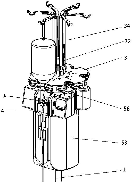
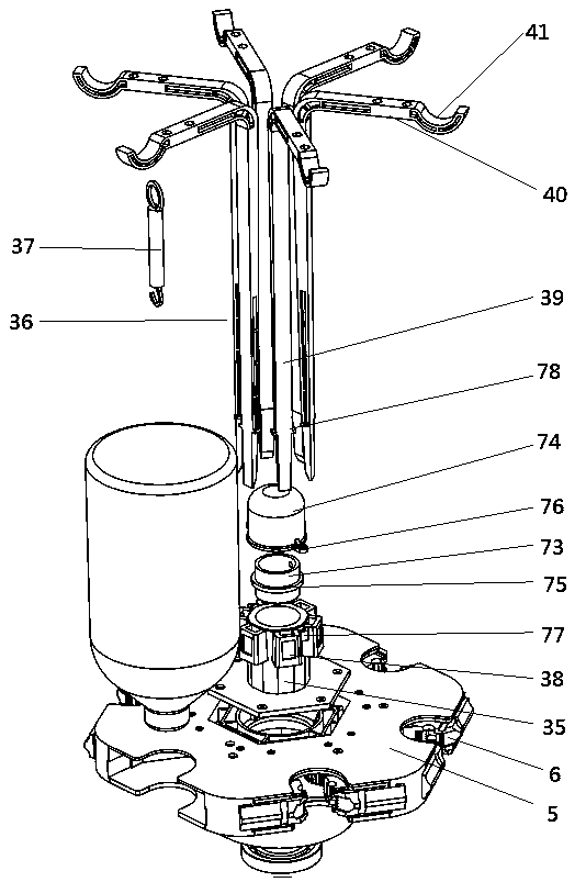
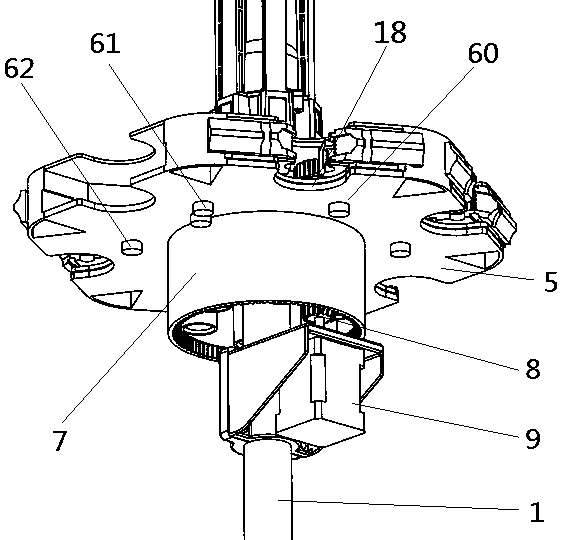
[0028] An intelligent infusion device for automatically changing infusion containers, characterized in that it includes a pillar 1 and a controller, the pillar 1 is provided with a bottle mouth automatic replacement mechanism 3 and a needle insertion mechanism 4, and the bottle mouth automatic replacement mechanism 3 It includes a rotating seat 5, a bearing, a bottle mouth clamping mechanism 6, a casing seat 7, a driving gear 8 and a driving motor 9,

[0029] The pillar 1 is provided with a revolving seat 5, which is fixedly connected to the pillar 1 via a bearing in the middle of the revolving seat 5. A bottle mouth clamping mechanism 6 is arranged around the periphery of the revolving seat 5, and a sleeve is provided at the lower end of the revolving seat 5. The pipe seat 7, the upper end of the casing seat 7 is fixedly connected with the rotating seat 5, and...


PUM


Abstract

The invention relates to the field of medical instruments, in particular to an intelligent infusion apparatus capable of automatically replacing an infusion container. The intelligent infusion apparatus comprises a support column and a controller, wherein the support column is provided with an automatic bottleneck replacing mechanism and a needle inserting and pulling mechanism; the automatic bottleneck replacing mechanism comprises a rotating seat, a bearing, bottleneck clamping mechanisms, a sleeve seat, a driving gear and a driving motor; the bottleneck clamping mechanisms are arranged on the periphery of the rotating seat in a circumferential array mode; each bottleneck clamping mechanism comprises a fixed frame, a first clamping seat, a second clamping seat, a first gear, a second gear and a spring; the needle inserting and pulling mechanism comprises a needle inserting and pulling bracket, a push rod motor, a needle pushing block, a needle tip clamp, a connecting plate and a liquid sensor; an infusion supporting mechanism is arranged at the upper end of the rotating seat; the infusion supporting mechanism comprises a supporting seat, a hook plate and a supporting spring; anda dripping speed detection mechanism and a needle tube pressing mechanism are arranged at the lower end of the needle inserting and pulling bracket. The infusion apparatus is ingenious in design, stable in bottleneck clamping, convenient, wide in applicability, monitorable for dripping speed, high in safety, disinfectable for bottleneck and positionable in rotation.

Description

technical field [0001] The invention relates to the field of medical devices, in particular to an intelligent infusion set for automatically replacing an infusion container. Background technique [0002] At present, the infusion operations in the hospital wards all use common infusion stands. Although multiple bottles of liquid medicine can be hung on each shelf, the bottles must be changed by a nurse, and the patient or family member needs to be taken care of. Informing the nurse to change the bottle, this process consumes a lot of manpower and time, especially in large hospitals with many wards, the infusion bottle change takes a lot of time and energy for the nurses, for this reason, Chinese patent CN109771731A discloses an automatic patient infusion bottle changer The bottle device includes a fixing seat, grooves distributed equidistantly on the outer wall of the top of the fixing seat, and an infusion bottle is placed on the inner wall of the groove, and a bearing is we...

Claims


Application Information

Patent Timeline
IPC IPC(8): A61M5/168A61M5/14A61L2/26A61L2/08
CPCA61L2/08A61L2/26A61L2202/23A61M5/1417A61M5/16827A61M5/16886
Inventor 马春峰郑军
Owner 河北华创志业医疗科技有限公司
Learn More