Petroleum filtering equipment

A filter equipment and oil technology, which is applied in the direction of filtration separation, purification by filtration, mobile filter element filter, etc., can solve the problems of affecting the environment, oil loss, oil falling out, etc., and achieve the effect of increasing the area

Active Publication Date: 2020-07-28
大庆美能科技有限公司
View PDF10 Cites 0 Cited by
  • Summary
  • Abstract
  • Description
  • Claims
  • Application Information

AI Technical Summary

Problems solved by technology

[0003] At present, the existing oil filtration equipment usually uses filter screens to filter impurities such as sediment and fine stones entrained in crude oil. When filtering crude oil, due to the viscosity of petroleum crude oil, it will adhere to the filter when it passes through the filter screen. On the impurities, the oil adhering to the impurities will fall out with the impurities when cleaning the impurities, resulting in the loss of oil and affecting the surrounding environment

Method used


Image

  • Petroleum filtering equipment
  • Petroleum filtering equipment
  • Petroleum filtering equipment

Examples


Embodiment 1

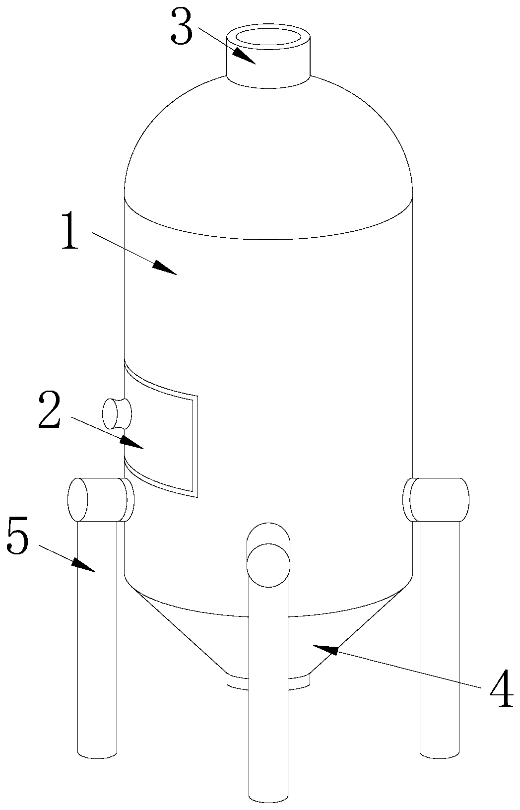
[0026] see Figure 1-Figure 4 :

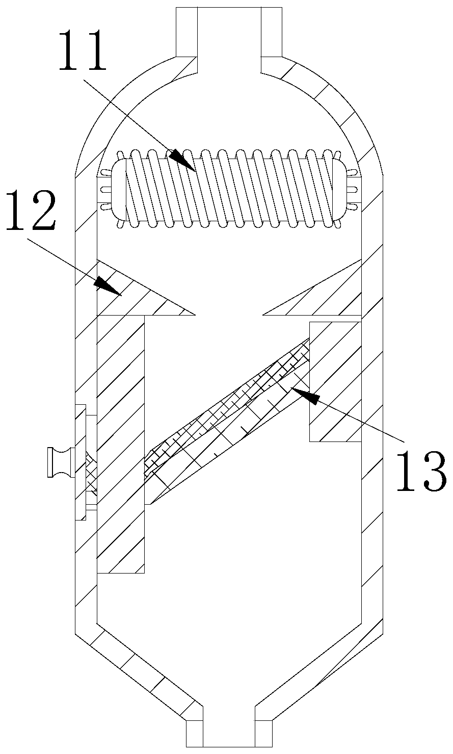
[0027] A kind of oil filtration equipment, its structure includes filter cartridge 1, impurity removal device 2, crude oil inlet 3, oil discharge port 4, bracket 5, said filter cartridge 1 is installed above the bracket 5, and said impurity removal device 2 is installed on On one side of the filter cartridge 1 surface, the crude oil inlet 3 is connected to the top of the filter cartridge 1 by welding, the oil discharge port 4 is embedded in the bottom of the filter cartridge 1, there are four brackets 5, and the filter cartridge 1 includes a mill Pressing device 11, guide plate 12, filter screen 13, described rolling device 11 is installed inside filter cartridge 1 and is positioned at crude oil inlet 3 just below, described guide plate 12 is connected to the inner wall of filter cartridge 1 by welding, and described filter screen 13 runs through the inner wall of the filter cartridge 1 and is located below the guide plate 12. The guide plate...

Embodiment 2

[0032] see Figure 5-Figure 6 :

[0033] In the figure, the filter screen 13 includes a fixed net 131 and a miscellaneous net 132. The fixed net 131 is connected to the bottom of the filter net 13 by welding, and the miscellaneous net 132 is connected to the upper surface of the fixed net 131 by movable engagement. The upper surface of the lower end of the miscellaneous net 132 is spoon-shaped, which is beneficial for storing filtered impurities.

[0034] In the figure, the two ends of the miscellaneous net 132 are respectively provided with a limiting device b1 and a cleaning device b2, the limiting device b1 is installed on the upper end of the miscellaneous net 132, and the cleaning device b2 is cooperatingly installed on the lower end of the miscellaneous net 132, The limiting device b1 and the cleaning device b2 are respectively embedded in the inner wall of the filter cartridge 1, and the surface is smooth and corrosion-resistant, so as to prevent crude oil from penetra...


PUM


Abstract

The invention discloses petroleum filtering equipment. The petroleum filtering equipment structurally comprises a filter cartridge, an impurity removal device, a crude oil inlet, an oil outlet, a support, a grinding device, a guide plate, a filter screen, fixing rods, rotating rollers, grinding blocks, extrusion plates, convex blocks, pressing plates, biting blocks, fixing nets, an impurity collection net, limiting devices, a cleaning device, reset springs, baffles, impact blocks, guide wheels, an impurity inlet, a water pool, an oil outlet hole, a water pump and water spraying pipes. The impact blocks impact the filter screen to allow the filter screen to shake, so impurities are prevented from staying on the filter screen and are allowed to fall to the spoon-shaped position of the impurity collection net; at the moment, the impurities are sprayed by the water spraying pipes, so the water flushes down adhered petroleum, the petroleum is discharged to the oil outlet through the oil outlet hole and is prevented from remaining on the impurities, and then the impurities on the impurity collection net are removed by pulling out the impurity removal device.

Description

technical field [0001] The invention relates to the petroleum field, in particular to a petroleum filtering device. Background technique [0002] Petroleum is known as the blood of the earth. It is mainly used as fuel oil and gasoline, and is also a product of many chemical industries. When oil is extracted, impurities such as sediment and fine stones in crude oil are filtered through oil filtration equipment to obtain pure oil. [0003] At present, the existing oil filtration equipment usually uses filter screens to filter impurities such as sediment and fine stones entrained in crude oil. When filtering crude oil, due to the viscosity of petroleum crude oil, it will adhere to the filter when it passes through the filter screen. On the impurities, the oil adhering to the impurities will fall out with the impurities when cleaning the impurities, resulting in the loss of oil and affecting the surrounding environment. Contents of the invention [0004] For the existing oil...

Claims


Application Information

Patent Timeline
IPC IPC(8): B01D33/03B01D33/74B01D33/64B01D33/42B01D33/48B02C4/08C10G31/09
CPCB01D33/03B01D33/42B01D33/48B01D33/64B01D33/74B02C4/08C10G31/09
Inventor 潘勇
Owner 大庆美能科技有限公司
Why Eureka
Try Eureka