
Batching system of concrete aggregate

A concrete aggregate and batching system technology, which is applied in batching and batching instruments, batching weighing instruments, clay preparation devices, etc., can solve the problem of high conveyor belt tension requirements, increased conveyor line costs, site occupation area, and long conveying distances And other issues

Active Publication Date: 2020-07-28
海宁市嘉海混凝土股份有限公司
View PDF6 Cites 3 Cited by
  • Summary
  • Abstract
  • Description
  • Claims
  • Application Information

AI Technical Summary

Problems solved by technology

[0002] Concrete is a building material formed by stirring and mixing various aggregates, additives and other materials. In order to reduce the transportation process and improve efficiency, it is usually necessary to transport various materials to a specified height or a specified location, and then mix them. Due to the many For the transportation of different specifications and types of aggregates, if multiple conveying lines are used, the cost and management difficulty will be greatly increased; the principle of zero waiting for the mixer needs to transport all aggregates to the designated location for storage, and then divide them into batches Mixing to the mixer for the first time, which requires the conveying line to convey different aggregates separately, and the separate conveying requires high tension of the conveyor belt, which is due to the different aggregates on the same conveyor belt. The quantity is almost the same, but the density is quite different, which leads to different requirements for the tension of the conveyor belt when transporting different materials. There are corresponding requirements for the temporary storage, distribution, and weighing of materials when transporting aggregates separately. It will increase the difficulty, but if the transmission distance is long and multiple transmission lines are used, the cost of the transmission line and the occupied area of ​​the site will be greatly increased

Method used


Image

  • Batching system of concrete aggregate
  • Batching system of concrete aggregate
  • Batching system of concrete aggregate

Examples


Embodiment Construction

[0023] The following are specific embodiments of the present invention combined with the accompanying drawings to further describe the technical solutions of the present invention, but the present invention is not limited to these embodiments.

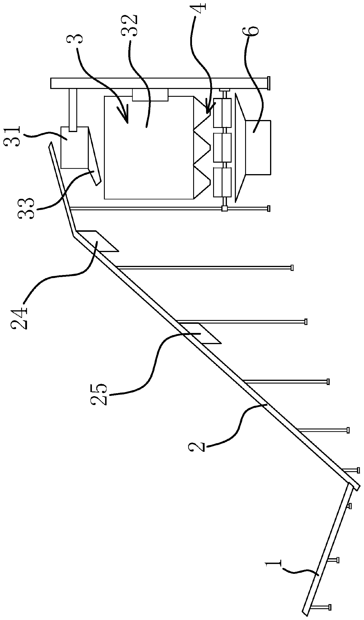
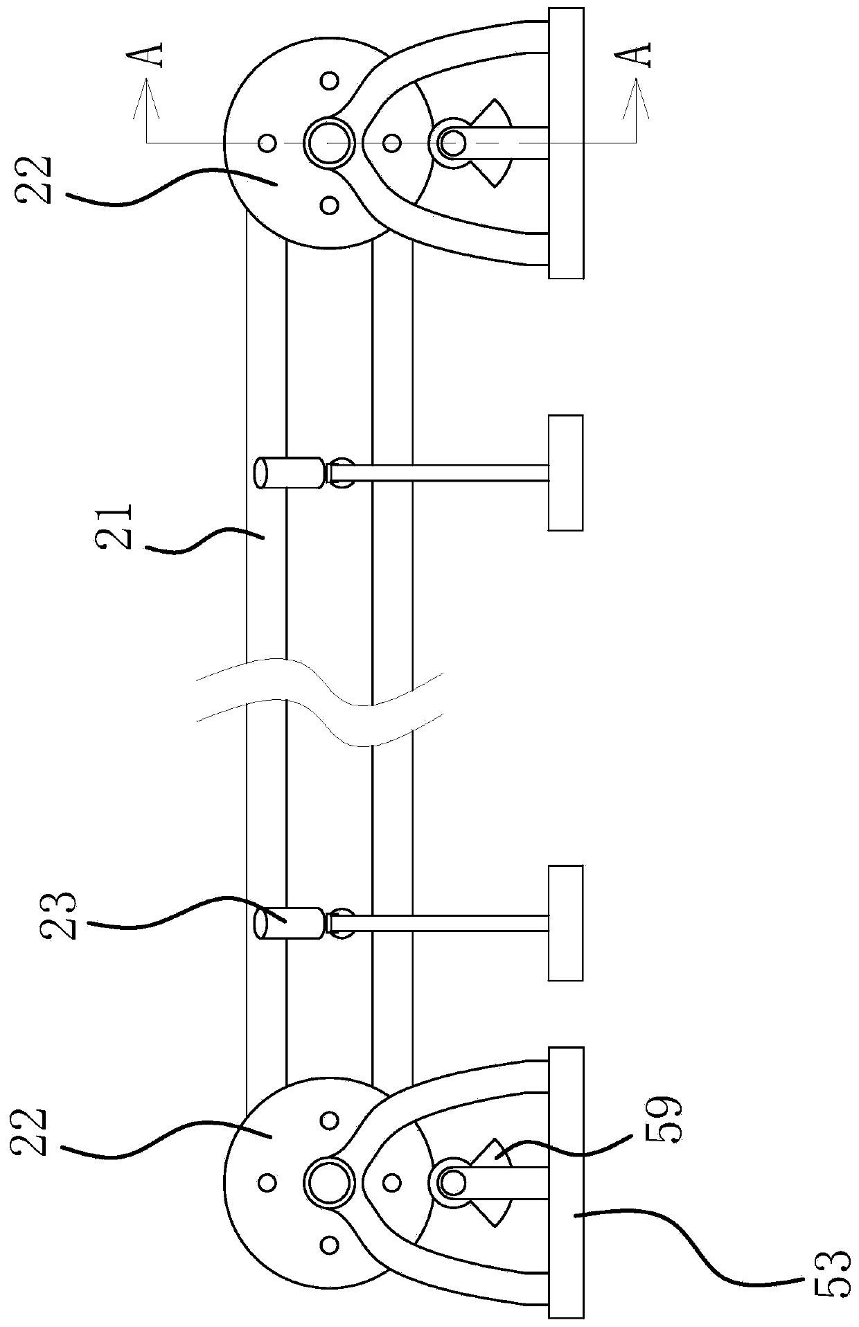
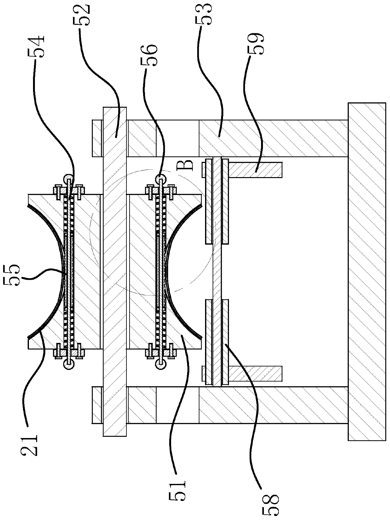
[0024] Such as figure 1 with Picture 9 As shown, this system includes a conveyor belt 1, a second conveyor belt 2, a material receiving and distributing device 3, a weighing and unloading mechanism 4, and a mixer 6. The first end of the conveyor belt 1 is fed, and the conveyor belt 2 is The head end receives the end of one end of the conveyor belt. The receiving and distributing device 3 includes a receiving barrel 31, a sub-packing tank 32, a separating hopper 33 and a first stepper motor 34. The end of the second-stage conveyor belt 2 is located at the end of the receiving barrel 31 Above, the hopper 33 is rotatably connected to the lower end of the receiving barrel 31, the housing of the first stepping motor 34 is fixed on the receivin...


PUM


Abstract

The invention provides a batching system of a concrete aggregate, which belongs to the technical field of construction. The batching system of the concrete aggregate comprises a receiving and distributing device, a weighing and unloading mechanism and a mixer. The end of a two-stage conveyor belt is located above a receiving barrel. The distributing hopper is rotatably connected to the lower end of the receiving barrel. The housing of a first stepping motor is fixed on the receiving barrel. A discharge end of the distributing hopper is inclined to the side deviating from the axis of the receiving barrel. The distributing hopper is provided with a transmission gear ring. A driving gear is fixedly arranged on an output shaft of the first stepping motor, and the driving gear meshes with the transmission ring gear. A plurality of temporary storage cavities are arranged in a sub-packing tank. The distributing hopper can be rotated to make the discharge end of a discharge hopper located above each temporary storage cavity. The weighing and unloading mechanism comprises a plurality of suspended weighing devices corresponding to the temporary storage cavity one-to-one. The suspended weighing devices can send the materials in the corresponding temporary storage cavities into the mixer according to the amount. The batching system of a concrete aggregate has the advantages of being able to divide different aggregates and the like.

Description

Technical field [0001] The invention belongs to the field of construction technology and relates to a batching system of concrete aggregates. Background technique [0002] Concrete is a building material formed by mixing various aggregates, additives and other materials. In order to reduce the transportation process and improve efficiency, it is usually necessary to transport all kinds of materials to a designated height or a designated position, and then mix them. For the transportation of different specifications and types of aggregates, if multiple conveyor lines are used, it will greatly increase the cost and management difficulty; the principle of zero waiting for the mixer requires that all aggregates be transported to a designated location for storage, and then divided into batches It is mixed to the mixer at the same time, which requires the conveyor line to transport different aggregates separately, which requires a higher tension on the conveyor belt. This is because di...

Claims


Application Information

Patent Timeline
IPC IPC(8): B28C7/04B28C7/06B28C7/02
CPCB28C7/02B28C7/0418B28C7/044B28C7/0481B28C7/06
Inventor 凌叙金陈晓清凌佳宇吴定杰江泽琪冯滨
Owner 海宁市嘉海混凝土股份有限公司
Learn More