Quick freezing system for graphene 3D printer
A 3D printer and refrigeration system technology, applied in the direction of additive processing, etc., can solve the problems of easy heating, long printing time, thin copper wire is not easy to fix and pick and place boards, etc., to achieve less heat and faster heat dissipation Effect
- Summary
- Abstract
- Description
- Claims
- Application Information
AI Technical Summary
Problems solved by technology
Method used
Image

Examples
Embodiment 1
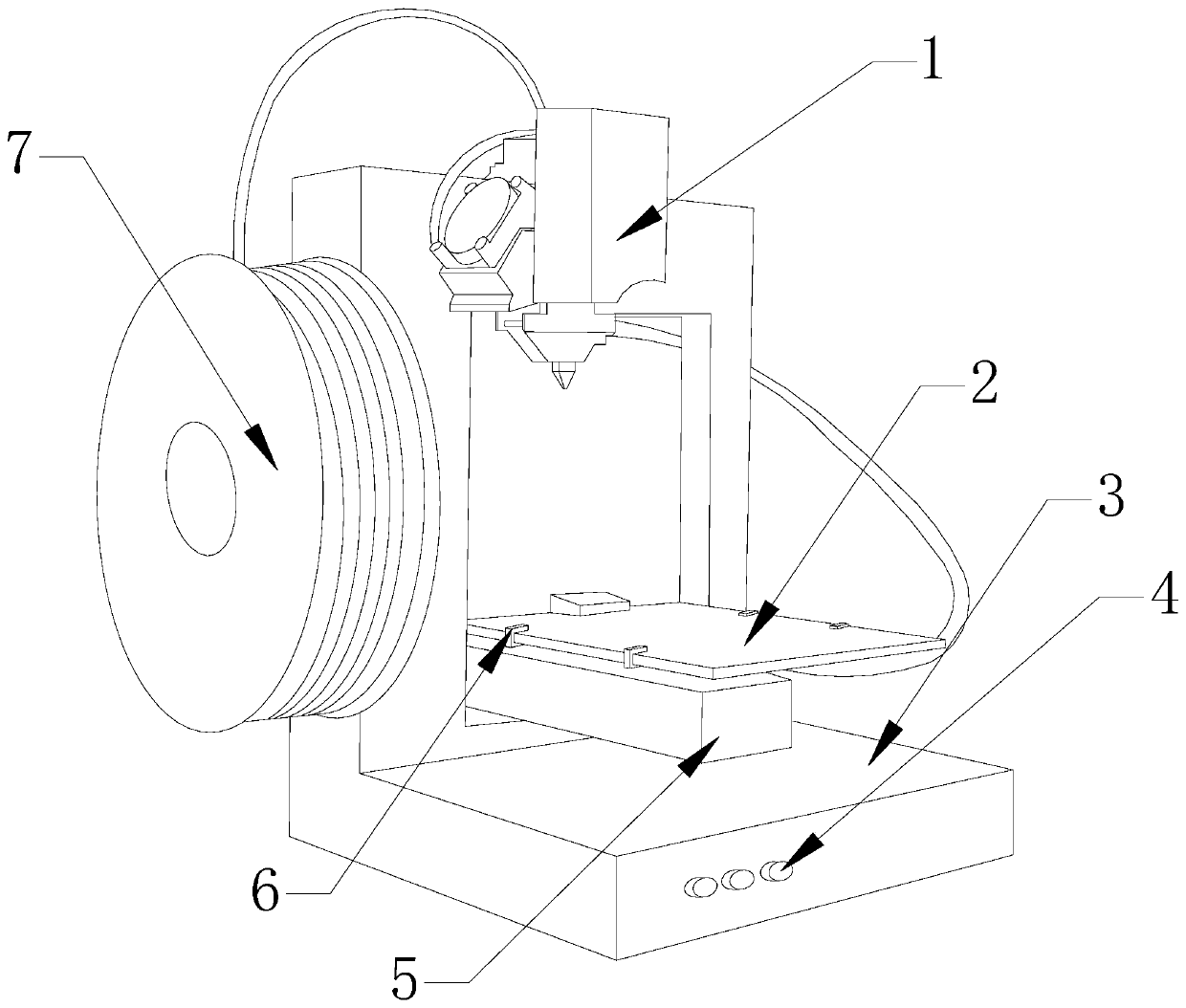
[0027] see Figure 1-Figure 4 , a quick freezing system for a graphene 3D printer, the invention provides a quick freezing system for a graphene 3D printer, its structure includes a heating head 1, a workbench 2, a body 3, a controller 4, a moving table 5, a fixed block 6. Roller 7, circulating cooler 15, the left side of the body 3 is equipped with a roller 7, the front of the body 3 is provided with a controller 4, the middle of the body 3 is slidingly connected with the mobile platform 5, the body 3 The upper part is mechanically connected with the heating head 1, the fixed block 6 is movably connected with the workbench 2 through a connecting shaft, the workbench 2 is installed above the mobile platform 5, and a recirculating cooler 15 is arranged at the rear of the body 3.
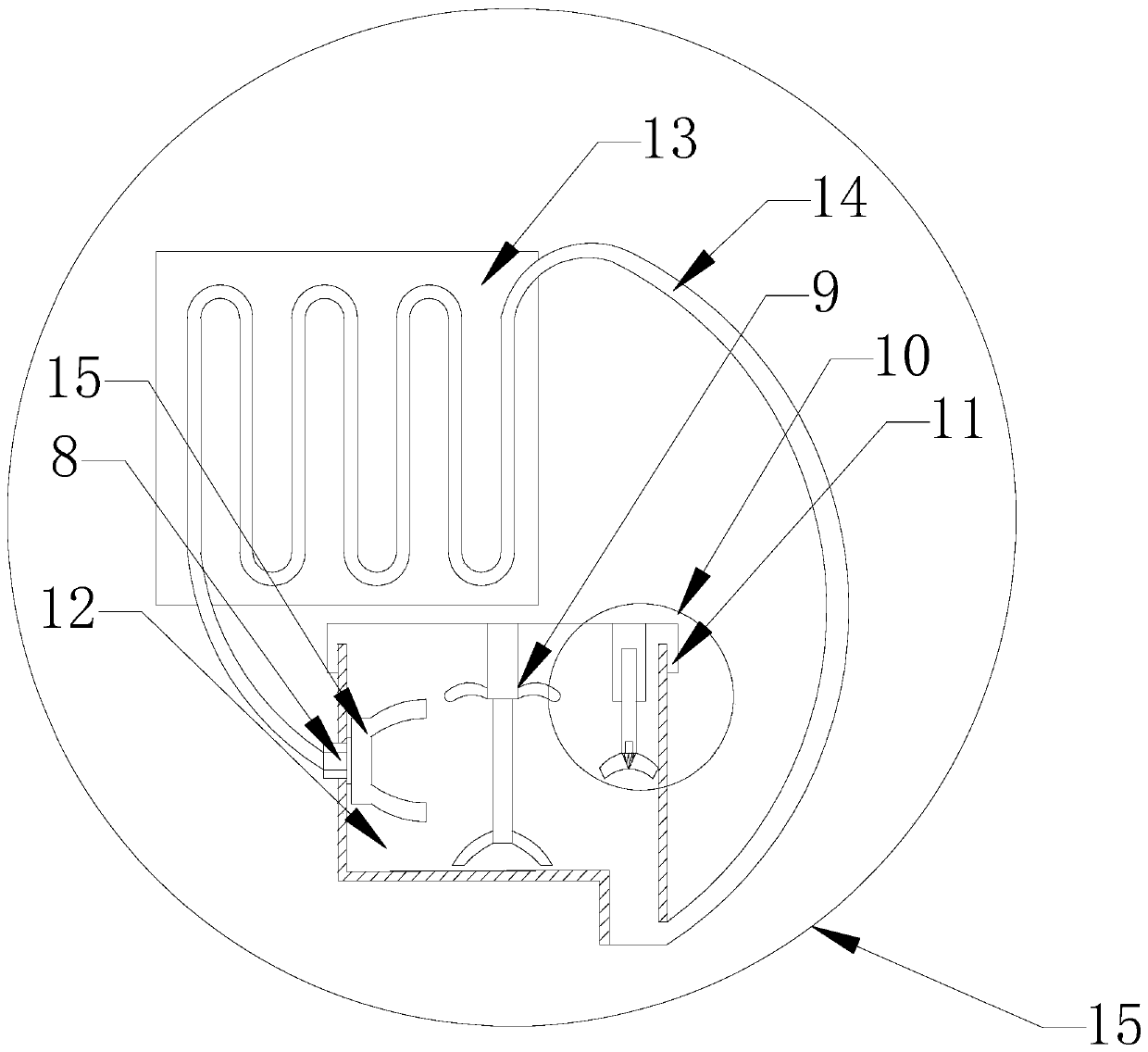
[0028] The circulating cooler 15 is composed of a disperser 8, an agitator 9, a compression pump 10, a box cover 11, a box body 12, a bottom plate 13, a conduit 14 and a rotating connection block 15, ...
Embodiment 2
[0035] see Figure 1-Figure 5, a quick freezing system for a graphene 3D printer, the invention provides a quick freezing system for a graphene 3D printer, its structure includes a heating head 1, a workbench 2, a body 3, a controller 4, a moving table 5, a fixed block 6. Roller 7, circulating cooler 15, the left side of the body 3 is equipped with a roller 7, the front of the body 3 is provided with a controller 4, the middle of the body 3 is slidingly connected with the mobile platform 5, the body 3 The upper part is mechanically connected with the heating head 1, the fixed block 6 is movably connected with the workbench 2 through a connecting shaft, the workbench 2 is installed above the mobile platform 5, and a recirculating cooler 15 is arranged at the rear of the body 3.
[0036] The circulating cooler 15 is composed of a disperser 8, an agitator 9, a compression pump 10, a box cover 11, a box body 12, a bottom plate 13, a conduit 14 and a rotating connection block 15, a...
PUM
 Abstract
Description
Claims
Application Information
 - Generate Ideas
- Intellectual Property
- Life Sciences
- Materials
- Tech Scout
- Unparalleled Data Quality
- Higher Quality Content
- 60% Fewer Hallucinations
Browse by: Latest US Patents, China's latest patents, Technical Efficacy Thesaurus, Application Domain, Technology Topic, Popular Technical Reports.
© 2025 PatSnap. All rights reserved.Legal|Privacy policy|Modern Slavery Act Transparency Statement|Sitemap|About US| Contact US: help@patsnap.com