Detergent feeding device and clothes washing machine

A detergent dispensing and rib technology, applied in the field of washing machines, can solve the problems of cracking of welding seams, affecting the normal operation of the washing machine, and burying hidden dangers for the safety of users, so as to avoid water leakage, improve safety and reliability, and reduce cracking. effect of risk

Pending Publication Date: 2020-07-28
QINGDAO HAIER DRUM WASHING MACHINE
6 Cites 0 Cited by

AI-Extracted Technical Summary

Problems solved by technology

[0002] The closed water circuit of the detergent dispensing device on the existing washing machine needs to be welded together by multiple parts to complete a series of complex functions. During the process of welding the two parts to each other, it is necessary to ensure the reliability of the welding. At present, the cover plate The water inlet channel in the cover i...

Method used

In the present embodiment, described lower cover 3 is installed on liquid storage box 2, is provided with at least one through hole 35 in the groove 7 of lower cover 3, and one end of through hole 35 is connected with airtight chamber, and another One end communicates with the inside of the water box 1 . The inner rib plate 5 and the outer rib plate 6 of the upper cover 4 and the lower cover 3 are butted together by equipment melting. After the welding is completed, the temperature of the air in the closed chamber gradually decreases, and a negative pressure is generated in the closed chamber, causing the cover plate to be under atmospheric pressure. Deformation under the action, and even the risk of cracking of the upper cover 4 and the lower cover 3, a through hole 35 is provided at the position corresponding to the lower cover 3 and the airtight chamber, which can balance the internal and exter...

Abstract

The invention discloses a detergent feeding device which comprises a water box and a liquid storage box arranged in the water box. The top part of the water box is formed by a cover plate; a water inlet passage for injecting water into the liquid storage box is arranged in a hollow chamber in the cover plate; a circle of sealing chamber extending along the periphery of the cover plate is arrangedon the periphery of the water inlet passage; and the water inlet passage and the outer part of the cover plate are separated by the sealing chamber. According to the detergent feeding device providedby the invention, rib plates on two sides of the sealing chamber achieves a double-layer protection effect on the water inlet passage, so that safety and reliability are realized, and the potential safety hazard of water leakage caused by the cracking of a fusion-welding crack due to the collision happened in the actual production or transportation process of a clothes washing machine is avoided.

Application Domain

Technology Topic

Image

  • Detergent feeding device and clothes washing machine
  • Detergent feeding device and clothes washing machine
  • Detergent feeding device and clothes washing machine

Examples

  • Experimental program(2)
  • Effect test(1)

Example Embodiment

[0030] Example one
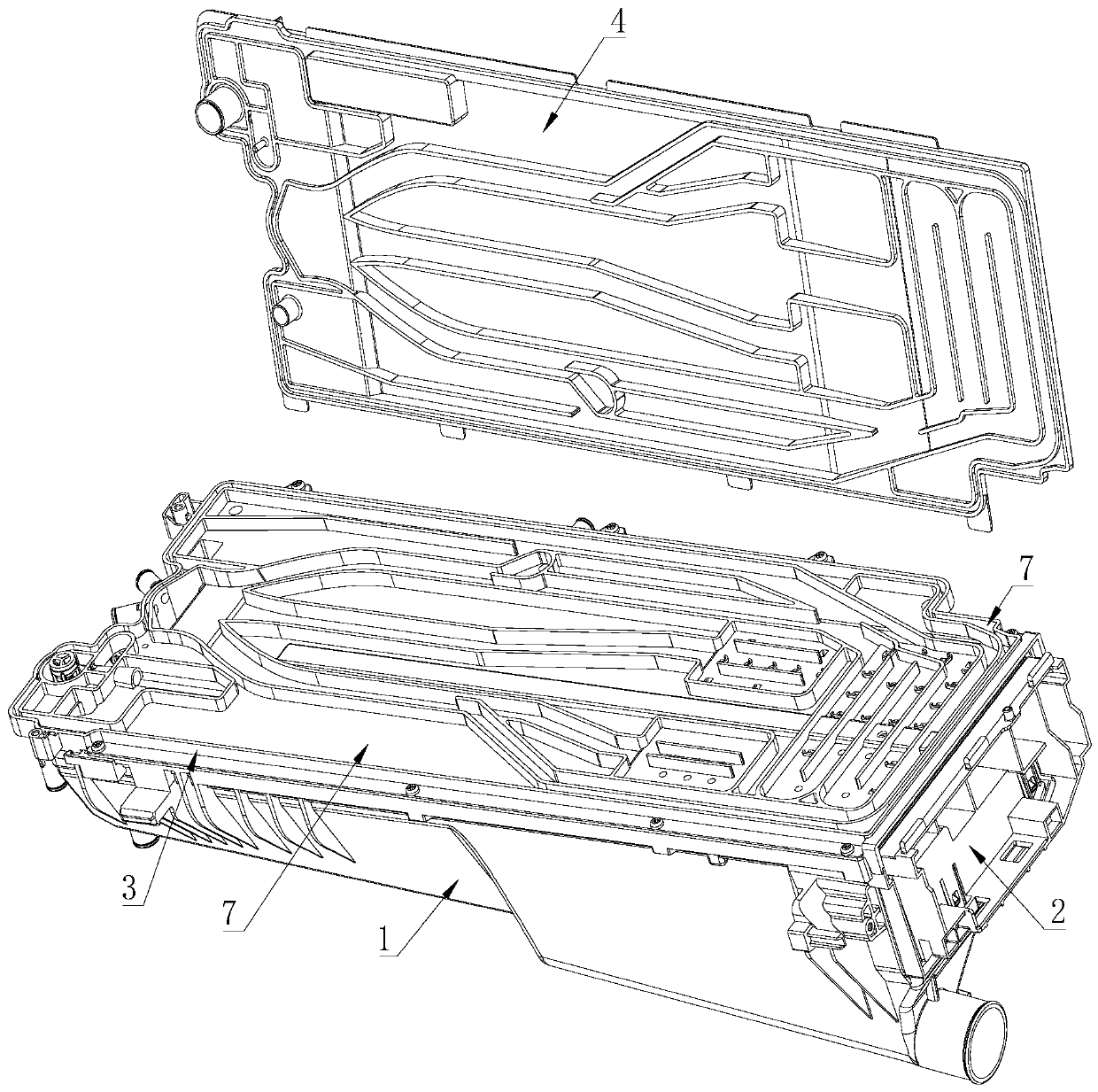
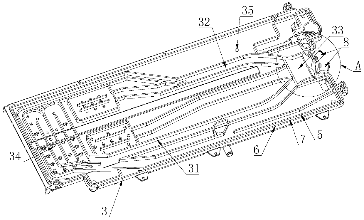
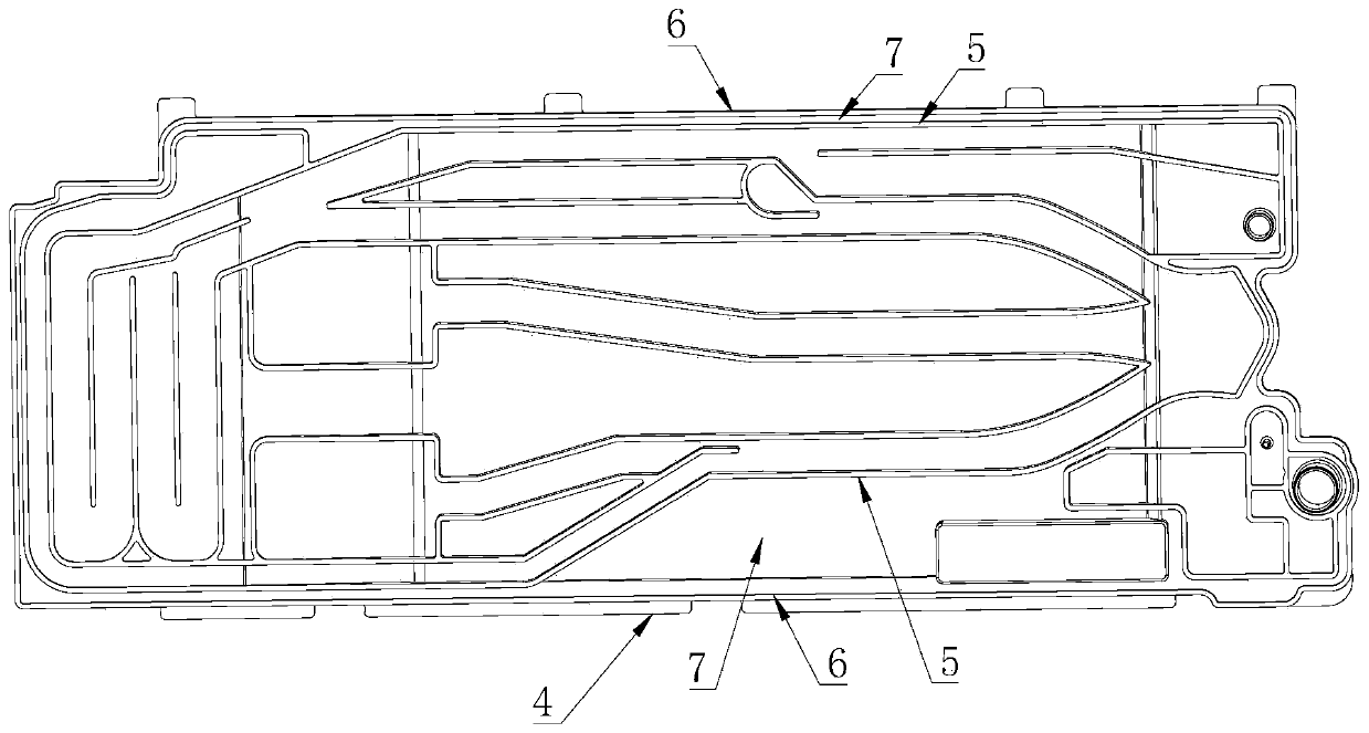
[0031] Such as Figure 1 to Figure 3 As shown, the detergent dispensing device described in the embodiment of the present invention includes a water box 1 and a liquid storage box 2 installed inside the water box 1. The top of the water box 1 is composed of a cover plate, and the inside of the cover plate The hollow chamber is provided with an inlet flow channel 32 for injecting water into the liquid storage box 2. A ring of inner ribs 5 is provided on the outer circumference of the inlet flow channel 32, and a ring of outer ribs 6 is provided on the outer circumference of the cover plate. It is spaced from the outer ribs 6 to form a closed chamber extending along the outer circumference of the cover plate. The entire closed chamber passes through. The inside of the closed chamber is provided with a through hole 35, and the closed chamber communicates with the outside of the cover through the through hole 35. .
[0032] In the embodiment of the present invention, the inner rib 5 and the outer rib 6 respectively form the outer peripheral wall of the water inlet channel 32 and the outer peripheral wall of the cover plate. The cover plate includes an upper cover 4 and a lower cover 3, and an upper cover 4 and/or The lower cover 3 is provided with an inlet flow channel 32, and the adjacent water inlet channels 32 are separated by a water diversion rib 31. The cover plate passes through the inner and outer ribs 6 and water diversion ribs of the upper cover 4 and the lower cover 3 31 corresponds to sealed welding. Collision during transportation and use may lead to cracking of the welded part. The water in the water inlet channel 32 is protected by the double-layer protection of the inner rib 5 and the outer rib 6. When the inner rib 5 is damaged, the water It will flow into the closed chamber, flow along the closed chamber to the through hole 35, and flow to the designated position through the through hole 35. In the present invention, the through hole 35 is in communication with the liquid storage box 2 and faces the water inlet channel 32 in the closed chamber. After any position of the side wall cracks, the water in the water inlet channel 32 flows through the crack to the closed chamber, flows along the inside of the closed chamber to the through hole 35, enters the top of the liquid storage box 2, and then flows into the water box 1. .
[0033] Through the above arrangement, the present invention provides double protection for the water inlet channel 32, which improves safety and reliability. The existing detergent dispensing device uses a layer of ribs to weld, and the washing machine collides during actual production or transportation. The cracking of the welding cracks causes water leakage, and the present invention effectively avoids the safety hazards of water leakage.

Example Embodiment

[0034] Example two
[0035] Such as Figure 1 to Figure 4 As shown, the detergent dispensing device described in the embodiment of the present invention is installed on a washing machine and automatically dispenses detergent solution into the washing machine. The detergent dispensing device includes a liquid storage box 2 containing detergent and a A cover plate for injecting water in the liquid storage box 2 is provided with an inlet flow channel 32, and the periphery of the inlet flow channel 32 is provided with an inner rib 5 and an outer rib 6 arranged at intervals, and an inner rib 5 and an outer rib 6 A circle of penetrating closed chamber is formed, and ribs on both sides of the closed chamber separate the water inlet channel 32 from the outside.
[0036] In this embodiment, the cover plate includes a lower cover 3 and an upper cover 4 that are buckled with each other. The upper cover 4 and the lower cover 3 are welded and fixed. The peripheries of the lower cover 3 and the upper cover 4 are provided with inner ribs 5 and outer The ribs 6, the inner ribs 5 and the outer ribs 6 enclose a circle of open grooves 7, and the grooves 7 of the lower cover 3 and the grooves 7 of the upper cover 4 cooperate to close the openings to form a closed chamber; or , The lower cover 3 is provided with inner ribs 5 and outer ribs 6, the upper cover 4 faces the side of the lower cover 3 buckled as a plane, and the inner ribs 5 and outer ribs 6 face the side of the upper cover 4 Correspondingly fixed on the surface of the upper cover 4, the space between the inner ribs 5, the outer ribs 6, the upper cover 4 and the lower cover 3 forms a sealed chamber.
[0037] In this embodiment, the outer ribs 6 extend along the outer shape of the lower cover 3 and/or the upper cover 4. The extension direction of the outer ribs 6 is the same as the outer circumference of the lower cover 3 and/or the upper cover 4. The inner ribs The plate 5 extends along the outer circumference of the water inlet channel 32, or the inner rib 5 and the outer rib 6 are arranged in parallel.
[0038] In this embodiment, the outer rib 6 of the lower cover 3 and the outer rib 6 of the upper cover 4 have the same shape, the inner rib 5 of the lower cover 3 and the inner rib 5 of the upper cover 4 have the same shape, and the outer ribs of the lower cover 3 The ribs 6 and the outer ribs 6 of the upper cover 4 are correspondingly sealed and welded, and the inner ribs 5 of the lower cover 3 and the inner ribs 5 of the upper cover 4 are correspondingly sealed and welded. The lower cover 3 and/or the upper cover 4 are provided with at least one water inlet channel 32 for guiding water flow. Each water inlet channel 32 corresponds to the area of ​​the liquid storage box 2 containing different detergents. The lower cover 3 is detachably fixed to the water On the top of the box 1, the liquid storage box 2 can be drawn inside the water box 1 and is located below the cover plate. The lower cover 3 is provided with water inlet channels 32 and water outlet holes 34 for filling the liquid storage box 2 with water. The water outlet 34 injects water into the liquid storage box 2 to dissolve the detergent and deliver the detergent to the washing machine. The adjacent water inlet channels 32 can be separated by a single-layer water diversion rib 31, or between adjacent water inlet channels 32 The space is separated by a double-layer water diversion rib 31, and the double-layer water diversion ribs 31 are spaced and sealed to form a cavity, and a through hole (not shown in the figure) communicating with the water box is provided in the cavity. The water-distributing rib 31 and the inner and outer ribs 6 from the lower cover 3 and/or the upper cover 4 to the upper cover 4 and/or the lower cover 3 protrude at the same height. The inner and outer ribs of the upper cover 4 and the lower cover 3 6 and the water diversion rib 31 are correspondingly welded and fixed.
[0039] In this embodiment, such as figure 2 with Figure 4 As shown, a water inlet pipe 8 is provided on the cover plate. One end of the water inlet pipe 8 is connected to the external water supply system, and the other end passes through the closed chamber to communicate with the water inlets 33 of the water inlet channels 32 of the water inlet channel 32; preferably, There are two water inlet pipes 8 on the cover, which can respectively inject cold water and hot water into the washing box.

PUM

no PUM

Description & Claims & Application Information

We can also present the details of the Description, Claims and Application information to help users get a comprehensive understanding of the technical details of the patent, such as background art, summary of invention, brief description of drawings, description of embodiments, and other original content. On the other hand, users can also determine the specific scope of protection of the technology through the list of claims; as well as understand the changes in the life cycle of the technology with the presentation of the patent timeline. Login to view more.

Similar technology patents

Hacking defending implementation method and device

Owner:MICRO DREAM TECHTRONIC NETWORK TECH CHINACO

Cheating prevention electronic weighing apparatus calibrating system and method

Owner:CHENGDU JIUZHOU ELECTRONIC INFORMATION SYSTEM CO LTD

Classification and recommendation of technical efficacy words

  • Prevent water leakage
  • Improve safety and reliability

Electric power supply device with electric shock protection function

Owner:国网安徽省电力有限公司铜陵市义安区供电公司
Why Eureka
Try Eureka