
Flexible energy-dissipating flow-guiding anti-scour device and application method

An anti-scour and flexible technology, applied in protection devices, water conservancy projects, artificial islands, etc., can solve the problems of lack of protection, insignificant protective effect, and large amount of materials, achieving good anti-scour effect, easy transportation and The effect of storage and simple structure

Pending Publication Date: 2020-07-28
中石化石油工程技术服务有限公司 +2
View PDF0 Cites 2 Cited by
  • Summary
  • Abstract
  • Description
  • Claims
  • Application Information

AI Technical Summary

Problems solved by technology

In practice, methods such as underwater riprap, expanded foundation protection, and concrete sinking pads have achieved a certain degree of erosion prevention and control effect, but solid objects such as underwater riprap are much more rigid than the seabed, and they are still harmful to the sea. The sediment on the bed has been severely washed away, leading to the occurrence of the "secondary erosion" problem on the seabed. The seawater continues to take away the sediment, and the stones sink. After a period of time, the stones will sink below the mud surface and have no protective effect. , so it is necessary to keep throwing stones to maintain the elevation of the mud surface
To ensure that the scour does not develop into the foundation within the service life, it is necessary to deal with a large area around the foundation, which is expensive and difficult to maintain later.
Pile body slit protection, pile front row pile protection and submerged sill protection are limited by water flow direction, and are mainly suitable for scour protection of pier piers in rivers. The protection effect is not obvious in the offshore environment, and it is laborious, time-consuming and consumes a lot of materials

Method used


Image

  • Flexible energy-dissipating flow-guiding anti-scour device and application method
  • Flexible energy-dissipating flow-guiding anti-scour device and application method
  • Flexible energy-dissipating flow-guiding anti-scour device and application method

Examples


Embodiment 1

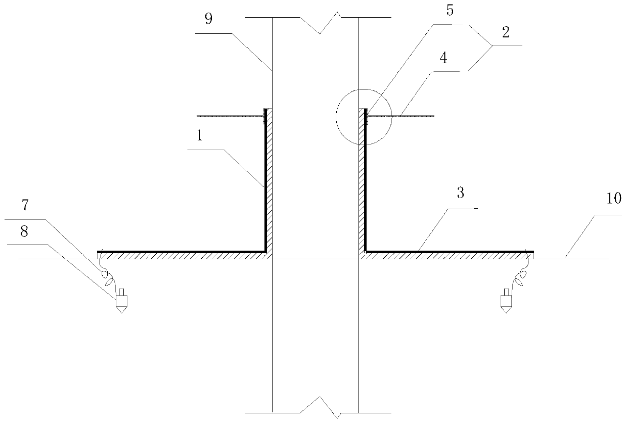
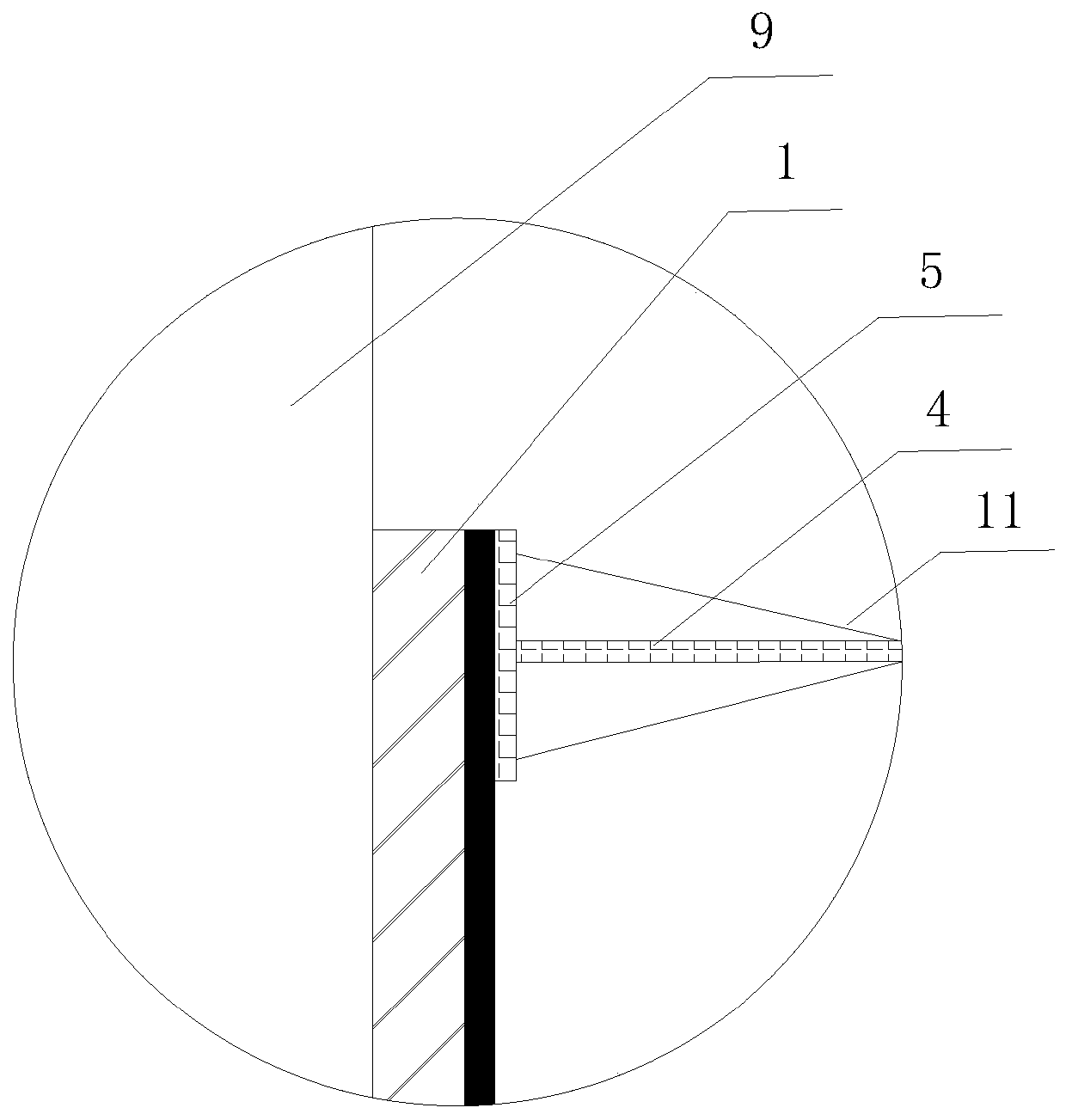
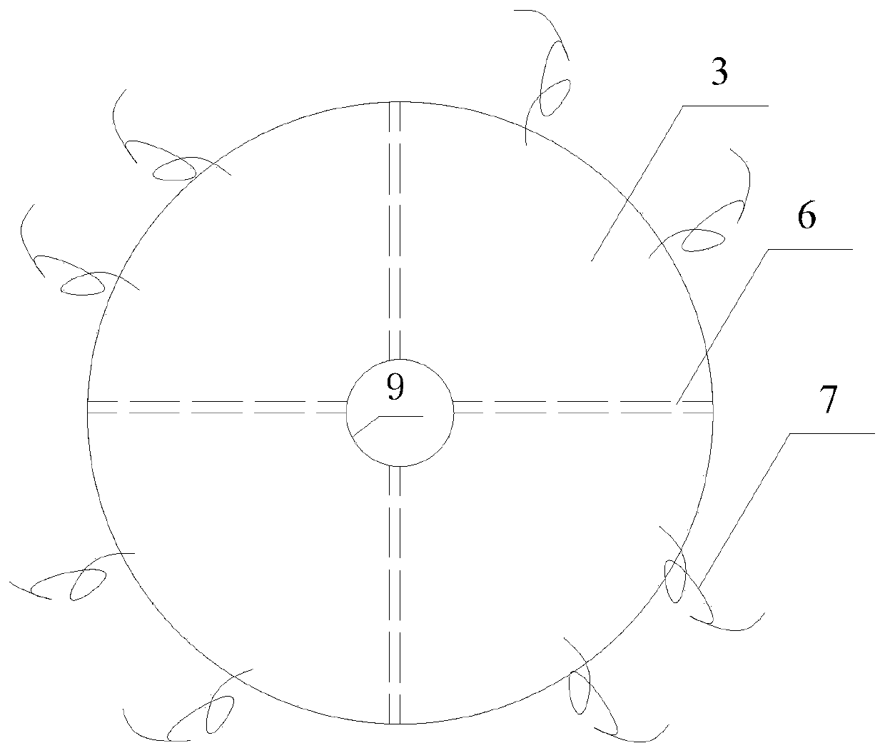
[0032] Example 1, with reference to the attached Figure 1-3 , a flexible energy dissipation and diversion anti-scour device, comprising: a flexible sheath 1, a rigid deflector 2, a flexible pad 3, an annular retaining ring 4, a short protective tube 5, an anchor rope 7 and an anchor 8. Wherein: the flexible sheath 1 has a rectangular structure, the two corresponding sides of the flexible sheath 1 are overlapped to form a cylindrical structure, the rigid deflector 2 is composed of an annular retainer 4 and a short sheath 5 connected, and the short sheath 5 is connected with the flexible After the sheath 1 is overlapped, a cylindrical structure is formed at the top to form a binding fit. The flexible cushion 3 is in the shape of a disk. The flexible cushion 3 has the same hole as the cylindrical structure after the flexible sheath 1 is overlapped. The inner edge of the pad 3 and the flexible sheath 1 are overlapped to form a fixed connection with the outer periphery of the bott...

Embodiment 2

[0038] Embodiment 2: an application method using the aforementioned flexible energy dissipation, diversion and anti-scour device, including: a flexible sheath is wrapped on a pile by a Velcro or a zipper, and a wire is connected, and a rigid deflector is configured. On the top of the flexible sheath, the flexible pad is laid around the pile foundation, and the inner edge of the flexible pad is connected to the flexible sheath through Velcro, zipper, wire rope, or is tied to the leg of the pile through a binding rope, and one end of the anchor rope is connected The other end of the flexible pad material is close to the outer edge, and the other end is set on the anchor. The anchor is driven into the seabed soil of a specified depth through the anchor grab, so that the outer edge of the flexible pad sags naturally and is perpendicular to the scouring surface to form an umbrella shaped protective net.

Embodiment 3

[0039] Embodiment 3: An application method using the aforementioned flexible energy dissipation and diversion anti-scour device, including: a flexible sheath is wrapped on a pile by a Velcro or a zipper, and a wire is connected, and a rigid deflector is arranged on the flexible On the top of the sheath, the slope-shaped protective structure is filled around the pile foundation, the flexible pad is laid around the pile foundation, and the inner edge of the flexible pad is connected with the flexible sheath through Velcro, On the pile legs, one end of the anchor rope is connected to the outer edge of the flexible pad material, and the other end is set on the anchor. And it is perpendicular to the scouring surface to form an umbrella-shaped protective net.


PUM


Abstract

The invention discloses a flexible energy-dissipating flow-guiding anti-scour device and an application method. The device is used for local scour protection of a pile foundation and comprises a flexible protective sleeve, a rigid guide plate and a flexible protective pad, wherein the flexible protective sleeve is arranged on a pile in a wrapping mode, the rigid guide plate is arranged at the topof the flexible protective sleeve, and the flexible protective pad is laid on the periphery of the pile foundation. According to the flexible energy-dissipating flow-guiding anti-scour device, the flexible protective sleeve is utilized to absorb kinetic energy of incoming flow, so that the velocity of the incoming flow is reduced; the rigid guide plate is utilized to block and disinfect descendingwater flow from a water surface of the pile foundation, so that the volume and direction of the descending water flow are changed, the descending water flow is forced to be divided towards two sides,and the intensity of a horseshoe-shaped vortex is reduced; the flexible protective pad is utilized to protect the bottom of the foundation, so that impact energy of the descending water flow is reduced, the energy of the incoming flow at the sea bottom mainly acts on the flexible protective pad, and consequently the effects of transporting and undercutting on sea bottom soil are avoided; and theflexible protective pad has good collaborative adaptability to sea beds with different pile foundations, thereby being suitable for various complicated sea bottom surfaces.

Description

technical field [0001] The invention relates to a foundation protection device for a fixed structure on water and an application method, in particular to a flexible energy dissipation, diversion and anti-scour device for a pile foundation, belonging to the technical fields of marine engineering and hydraulic engineering. [0002] technical background [0003] The pile foundation mentioned in the present invention is mainly the foundation part of bridge piers or piles driven into the seabed as supports of bridges, wharfs, trestle roads or fixed platforms. In the shallow sea and intertidal zone to build wind turbine foundations, bridges, jacket platforms, jack-up platforms and other fixed structures on the water, due to the action of tides and ocean currents, the soil around the foundations will be washed away, taking away piles and foundations. The surrounding sediment will reduce the bearing capacity of the pile body. When the pile foundation is exposed to a certain extent, i...

Claims


Application Information

Patent Timeline
Patent Type & Authority Applications(China)
IPC IPC(8): E02B17/00E02D31/00
CPCE02B17/003E02D31/00
Inventor 王天英张士华田海庆张爱恩崔希君张红胜柏健崔青魏羲尹慧敏任红伟
Owner 中石化石油工程技术服务有限公司
Learn More