Two-way coupling shear damper, shock-absorbing frame structure system

A two-way coupling, shock-absorbing frame technology, applied in the direction of earthquake resistance, building components, building types, etc., can solve problems such as difficulty in adapting to two-way coupling deformation, low seismic performance of dampers, unstable and reliable bearing capacity, stiffness and energy dissipation capacity, etc. , to avoid buckling damage or breakage and reduce damage

Active Publication Date: 2021-09-07
BEIJING UNIV OF CIVIL ENG & ARCHITECTURE
View PDF0 Cites 0 Cited by
  • Summary
  • Abstract
  • Description
  • Claims
  • Application Information

AI Technical Summary

Problems solved by technology

Therefore, the existing metal shear dampers are difficult to adapt to two-way coupling deformation, and cannot provide stable and reliable bearing capacity, stiffness and energy dissipation capacity under two-way coupling deformation
At present, when the shear damper shock-absorbing frame structure, which only considers the in-plane mechanical behavior of the damper in the main axis direction, exhibits two-way coupling deformation characteristics under actual earthquake action, the seismic performance of the structure may be lower than the design expected level
[0005] At present, under the action of horizontal reciprocating earthquakes on metal shear dampers commonly used in construction projects, the energy-dissipating steel plate will also be subjected to tensile force in addition to shear force, and the energy-dissipating steel plate will buckle out of plane or the weld seam will break under repeated tension and compression. And other phenomena, which in turn lead to the seismic performance of the damper is lower than the expected level of the design, making it difficult to ensure the safety of the infill wall under the action of the earthquake, which seriously threatens the sustainability of the building's function after the earthquake

Method used


Image

  • Two-way coupling shear damper, shock-absorbing frame structure system
  • Two-way coupling shear damper, shock-absorbing frame structure system
  • Two-way coupling shear damper, shock-absorbing frame structure system

Examples


Embodiment Construction

[0038] In order to make the purpose, technical solutions and advantages of the invention clearer, the technical solutions in the invention will be clearly described below in conjunction with the accompanying drawings in the invention. Obviously, the described embodiments are part of the embodiments of the invention, not all of them. Example. Based on the embodiments of the invention, all other embodiments obtained by persons of ordinary skill in the art without making creative efforts belong to the protection scope of the invention.

[0039] In the description of the embodiments of the present invention, it should be noted that the terms "center", "longitudinal", "transverse", "upper", "lower", "front", "rear", "left", "right" , "vertical", "horizontal", "top", "bottom", "inner", "outer" and other indicated orientations or positional relationships are based on the orientations or positional relationships shown in the drawings, and are only for the convenience of describing thi...


PUM


Abstract

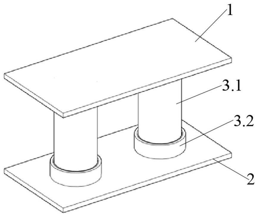
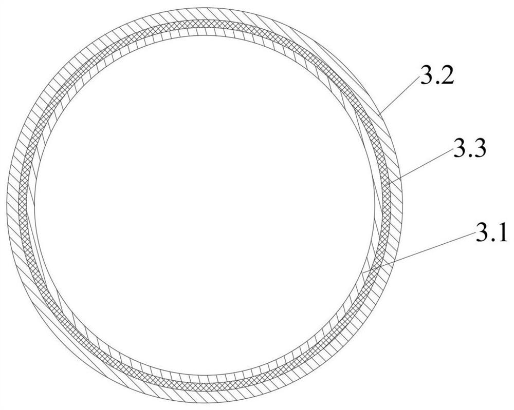
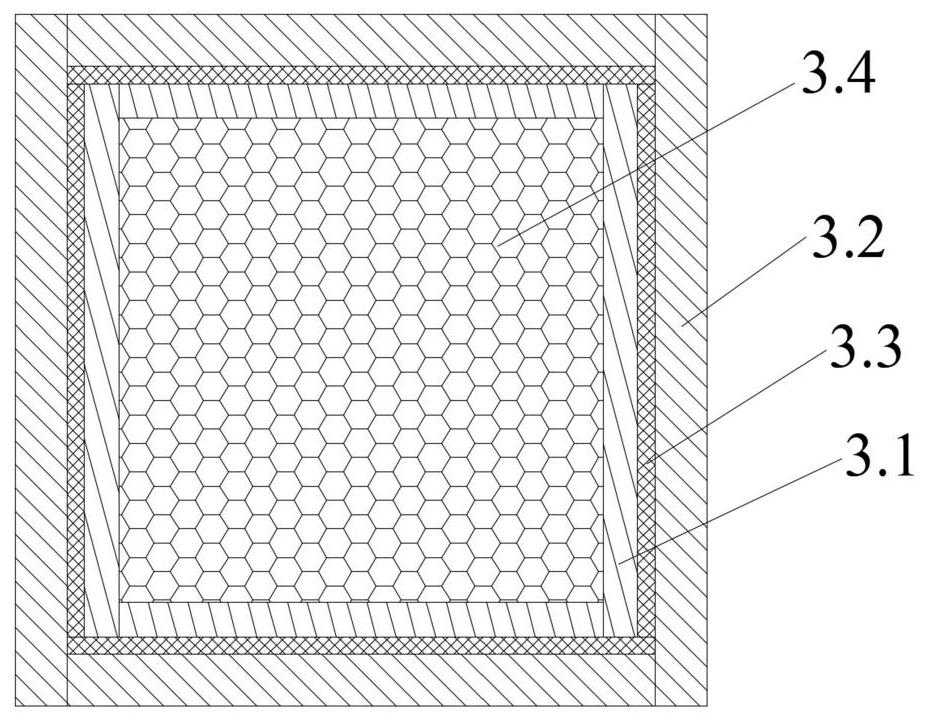
The invention relates to the field of building construction, and provides a two-way coupled shear damper and shock-absorbing frame structure system. The damper includes an upper end plate, a lower end plate, and an energy dissipation assembly arranged between the upper end plate and the lower end plate. The energy dissipation assembly includes an energy dissipation tube fixed on the upper end plate and a fixed tube fixed on the lower end plate; the length of the energy dissipation tube is longer than the fixed The length of the tube, the end of the energy dissipation tube facing away from the upper end plate is slidably inserted into the fixed tube, a smooth layer is formed between the fixed tube and the energy dissipation tube, and the smooth layer is attached and fixed on the inner wall of the fixed tube. The structural system includes a main frame structure, a first infill wall panel, a second infill wall panel, and two-way coupled shear dampers. The invention not only avoids the buckling damage or breaking of the energy dissipation tube, but also realizes the coordination of the deformation and damage mechanism among the main body frame structure, the damper, the first infill wallboard and the second infill wallboard, and significantly reduces the stress of the second infill wallboard. The damage of the first infill wall panel and the second infill wall panel under two-way coupled earthquake action.

Description

technical field [0001] The invention relates to the technical field of building construction, in particular to a two-way coupled shear damper and shock absorbing frame structure system. Background technique [0002] The frame structure is widely used in buildings such as multi-storey residences, factories, shops, office buildings, hospitals, teaching buildings and hotels because of its advantages of flexible layout and large interior space. In the frame structure, infill walls are generally built for functional division and external enclosure. [0003] A large number of actual earthquake damage records show that most of the frame structures did not collapse after the earthquake, but the infill walls built in the frame structures were severely damaged, which led to the need for a lot of manpower and material resources to repair the building, otherwise it could not be put into use. However, the "three-level and two-stage" design method in the code for seismic design of buildi...

Claims


Application Information

Patent Timeline
Patent Type & Authority Patents(China)
IPC IPC(8): E04B1/98E04H9/02
CPCE04B1/98E04H9/02
Inventor 杨参天閤东东苗启松陈曦解琳琳种迅刘谦敏刘长东
Owner BEIJING UNIV OF CIVIL ENG & ARCHITECTURE
Why Eureka
Try Eureka