Portable type gas charging and discharging device
A charging and deflation, portable technology, applied in the direction of pump device, circuit device, battery circuit device, etc., can solve the problems of high-pressure vortex fan heavy weight, inconvenient to carry, etc., to achieve the effect of shortening the inflation time, being easy to carry, and reducing the volume
- Summary
- Abstract
- Description
- Claims
- Application Information
AI Technical Summary
Problems solved by technology
Method used
Image
Examples
Embodiment 1
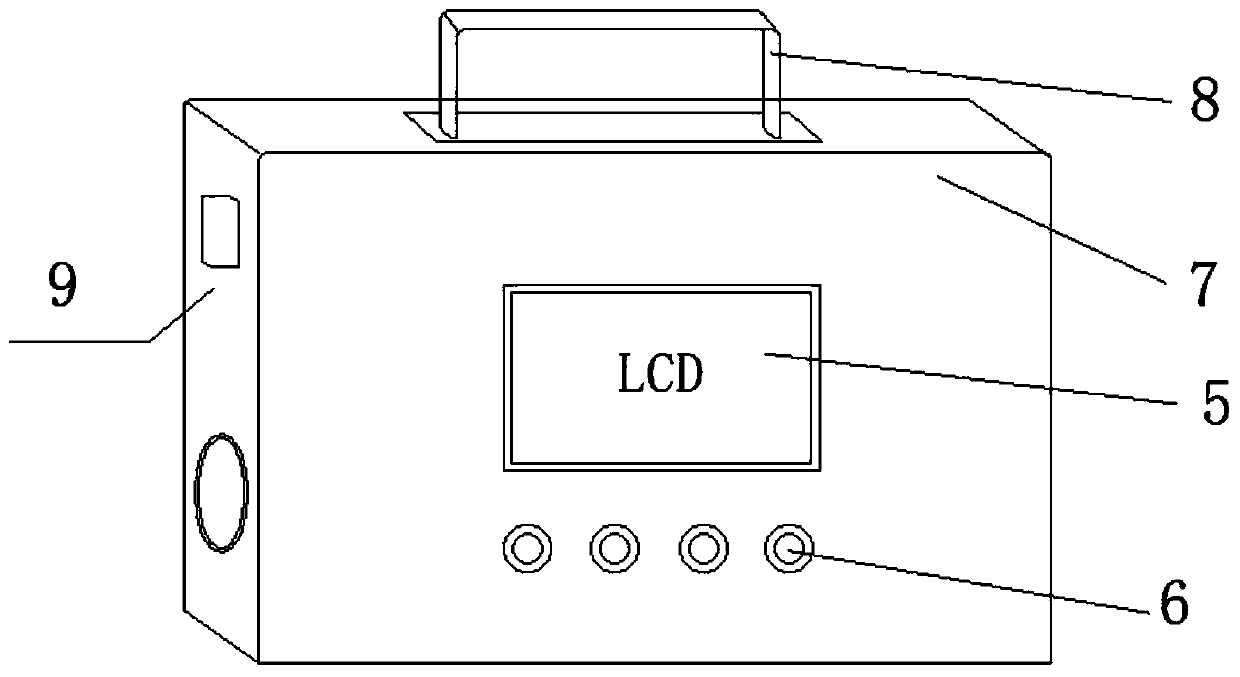
[0044] The portable inflation and deflation device provided by the present invention includes a case 7 and a control assembly and a blower 4 both placed in the case 7 .
[0045] see figure 2, in the present embodiment, cabinet 7 is a cabinet structure, and material is aluminum+plywood, and cabinet 7 is also provided with handle 8, and handle 8 is designed as embedded, easy to carry.
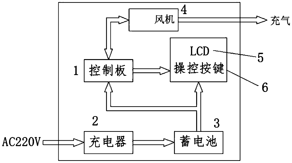
[0046] see figure 1 , in this embodiment, the control assembly includes a charger 2, a storage battery 3, a control board 1 and a display 5; the charger 2, the storage battery 3, the control board 1 and the fan 4 are placed at the bottom of the chassis 7; the display 5 is arranged on the chassis 7, and the display 5 is connected to the control board 1; the battery 3 is connected to the charger 2, the control board 1 and the display 5 respectively; the control terminal of the control board 1 is connected to the fan 4; the charger 2 charges the battery 3, The storage battery 3 supplies power to ...
Embodiment 2
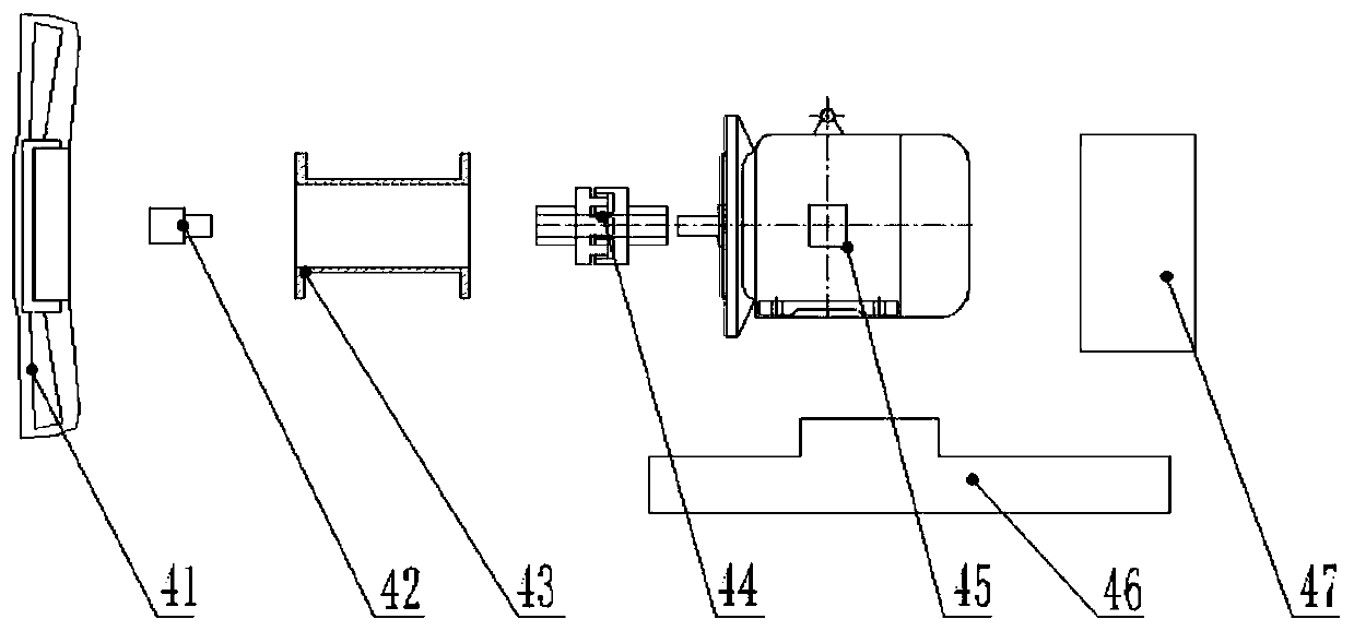
[0052] On the basis of embodiment 1, see image 3 as well as Figure 4 , the fan 4 comprises a DC motor 45, a base 46, a fan shaft 42 and a fan controller 47; the DC motor 45 and the fan controller 47 are placed on the base 46 respectively; The other end of the fan shaft 42 is provided with a fan impeller 41; the coupling 44 and the outside of the fan shaft 42 are fixed by a fixed flange 43; the control board 1 is connected with the fan controller 47, supplies power to the fan 4 and controls the fan impeller 41 Rotational wind speed; the air outlet 10 communicates with the fan impeller 41 .
[0053] see Figure 5 , when the present embodiment is implemented, the wiring between the parts is that the charger 2, the storage battery 3, the power indicator light (control button 6) and the fan controller 47 are connected to each other by red and black two strands of wires, and the charger 2. Connect to the 220V AC power socket to charge the battery 3. An air switch is set between...
Embodiment 3
[0070] On the basis of Embodiment 2, a first air outlet and a second air outlet are arranged at the bottom of the fan 4, and a gas flow sensor and a pressure transmitter are arranged on the first air outlet. A temperature sensor is set on the casing of the DC motor 45 .
[0071] Both the first air outlet and the second air outlet are tubular; and one end is fixed on the bottom of the fan 4 . During implementation, the diameters of the first air inlet and the first air outlet are both Φ50mm; the diameter of the second air inlet is also Φ50mm, and the diameter of the second air outlet is Φ20mm, which is convenient for connecting with the inflated equipment.
[0072] Preferably, the model of the gas flow sensor is HFS4001, MF5000 or FS4008. These gas flow sensors are small in size and can monitor the air outlet flow through the first air outlet in real time, which is convenient for calculating the instantaneous and cumulative flow of the air outlet at the air outlet. The control...
PUM
 Abstract
Description
Claims
Application Information
 - R&D
- Intellectual Property
- Life Sciences
- Materials
- Tech Scout
- Unparalleled Data Quality
- Higher Quality Content
- 60% Fewer Hallucinations
Browse by: Latest US Patents, China's latest patents, Technical Efficacy Thesaurus, Application Domain, Technology Topic, Popular Technical Reports.
© 2025 PatSnap. All rights reserved.Legal|Privacy policy|Modern Slavery Act Transparency Statement|Sitemap|About US| Contact US: help@patsnap.com


