Manifold device for high pressure mass flow meter and manifold assembly

A mass flow meter and manifold technology, which is applied in mass flow measuring devices, direct mass flow meters, measuring flow/mass flow, etc., can solve the problems of large size of manifold device 1, large consumption of welding materials, and increase of materials.

Pending Publication Date: 2020-07-28
MICRO MOTION INC
View PDF13 Cites 0 Cited by
  • Summary
  • Abstract
  • Description
  • Claims
  • Application Information

AI Technical Summary

Problems solved by technology

To complete the above-mentioned welding structure, it is necessary to weld the welding end 21 of the pipe joint 2 and the welding parts 12 and 13 at both ends of the manifold device 1 in circles until the welding part is filled with welding material, which takes a long time to weld and consumes a lot of welding material
And because the diameters of the large holes 121 and 131 at both ends of the manifold device 1 are relatively large, in order to meet the pressure requirements, the manifold device 1 needs a thicker outer diameter, thus resulting in the oversized size of the entire manifold device 1
In addition, since the pipe joint 2 is a non-standard part, different sizes need to design different pipe joints 2, which will lead to an increase in materials

Method used


Image

  • Manifold device for high pressure mass flow meter and manifold assembly
  • Manifold device for high pressure mass flow meter and manifold assembly
  • Manifold device for high pressure mass flow meter and manifold assembly

Examples


Embodiment Construction

[0029] The foregoing and other features and characteristics of the present application will become more apparent from the following detailed description with reference to the accompanying drawings, which are by way of illustration only and not necessarily drawn to scale. The same reference numerals are used to designate the same parts in the figures. The directions of "front", "left", and "upper" described in the embodiments of the present invention are based on Figure 6 The "X", "Y" and "Z" directions pointed by the arrows in the coordinates shown in , and the directions of "back", "right" and "down" are Figure 6 The direction opposite to the "X", "Y" and "Z" directions pointed by the arrows in the coordinates shown in .

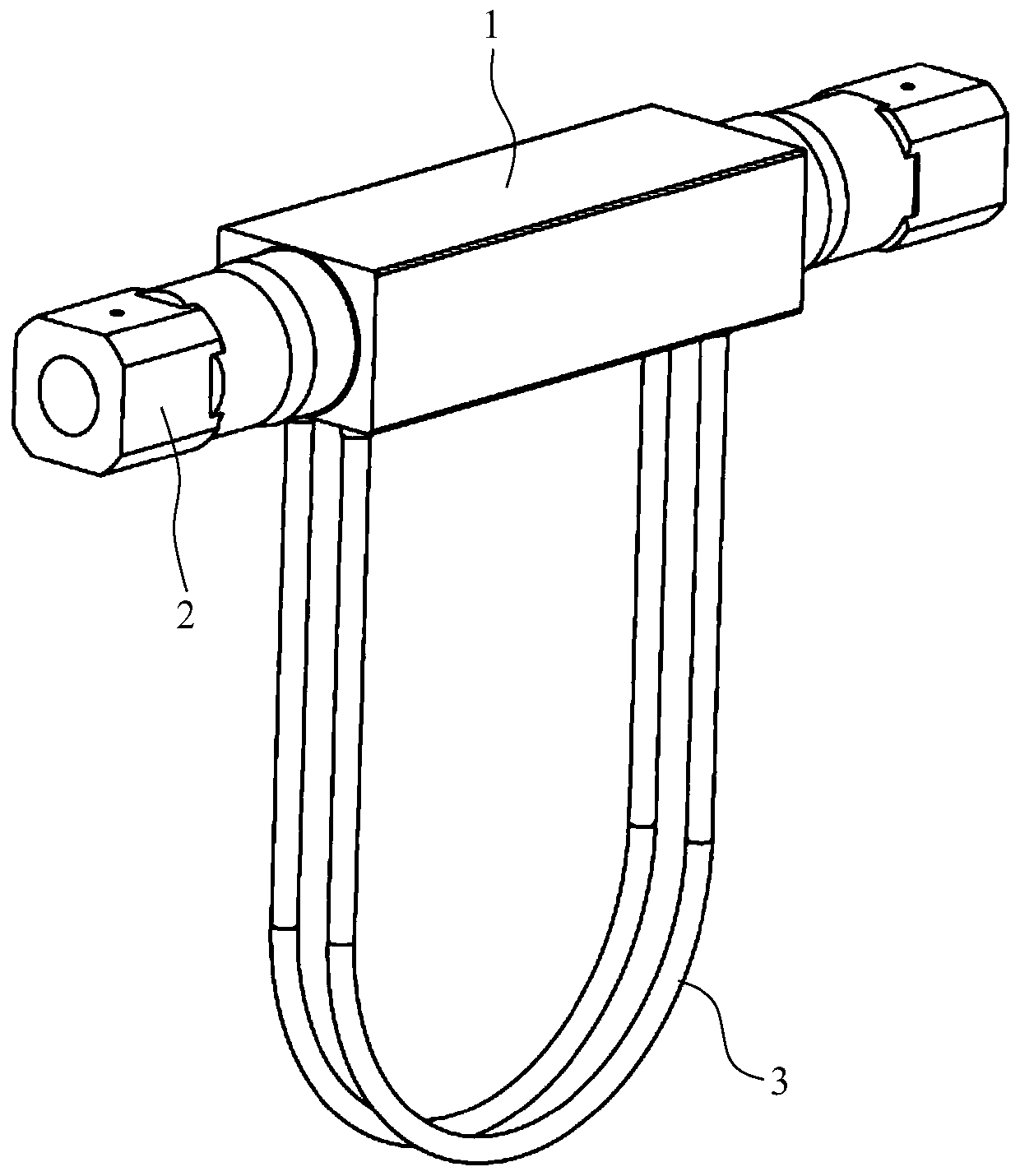
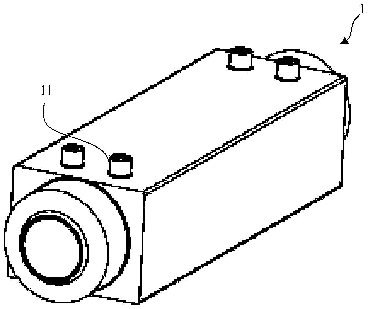
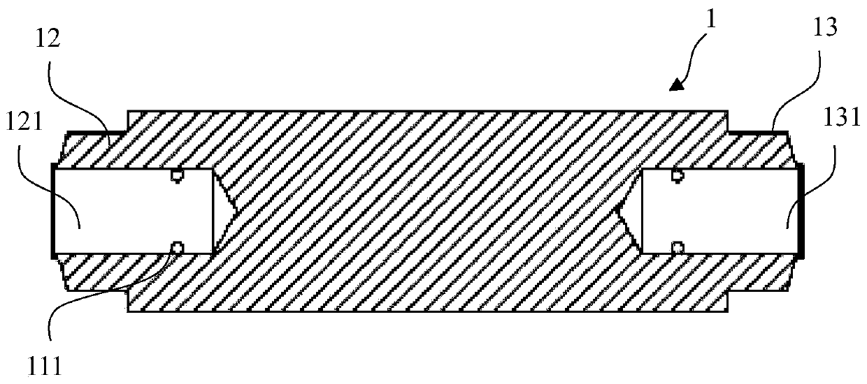
[0030] Figure 6 is a perspective view of a manifold device 100 for a high pressure mass flow meter according to an embodiment of the present invention. Depend on Figure 6 It can be seen that the manifold device 100 includes a rectangular body 110, t...


PUM


Abstract

The invention relates to a manifold device (100) for a high pressure mass flow meter and a manifold assembly (10). The manifold device (100) comprises a rectangular body (110); the upper surface of the rectangular body (110) is provided with two sets of bosses (120) connected with measuring tubes (400); boss channels (121) are formed in the bosses; threaded holes (130) are formed in the two end faces of the rectangular body (110) respectively; and each threaded hole (130) is in fluid communication with the boss channels (121) in the corresponding set of bosses (120).

Description

technical field [0001] The present invention relates to manifold devices and manifold assemblies for mass flow meters. Background technique [0002] The statements in this section merely provide background information related to the present disclosure and may not constitute prior art. [0003] A Coriolis mass flowmeter (CMF for short) is a mass flow meter made using the principle of Coriolis force. density. figure 1 Shown is a current manifold assembly for a high-pressure mass flowmeter, which includes a manifold device 1, a pipe joint 2, and a measuring tube 3, wherein the manifold device 1 and the pipe joint 2 are connected by welding, which It is a sealing connection method adopted when common seals such as sealing rings are easily deformed and invalidated in high-pressure fluid. figure 2 and image 3 A manifold arrangement 1 is shown. The upper surface of the manifold device 1 is provided with a boss 11 connected with the measuring tube 3 , wherein a small hole 111...

Claims


Application Information

Patent Timeline
Patent Type & Authority Applications(China)
IPC IPC(8): G01F1/84
CPCG01F1/8413
Inventor 王东晓加尼特·罗伯徐迎雪赵恒
Owner MICRO MOTION INC
Why Eureka
Try Eureka