
Beam structure initial state recognition method based on displacement and corner

A technology of initial state and identification method, applied in the field of civil engineering, can solve problems such as inconsistency of initial state, evaluation, damage identification deviation, etc., and achieve the effect of fewer influencing factors, simple and convenient operation, and strong operability

Active Publication Date: 2020-07-28
GUANGXI TRANSPORTATION SCI & TECH GRP CO LTD
View PDF8 Cites 7 Cited by
  • Summary
  • Abstract
  • Description
  • Claims
  • Application Information

AI Technical Summary

Problems solved by technology

However, the design state is idealized, and the initial state of the actual structure is inconsistent with the design state. If it is used equally, it will bring deviations to subsequent evaluation, damage identification, etc., and this deviation cannot be ignored

Method used

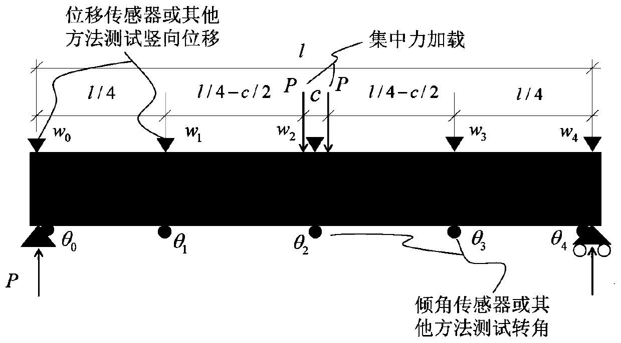

Image

  • Beam structure initial state recognition method based on displacement and corner
  • Beam structure initial state recognition method based on displacement and corner
  • Beam structure initial state recognition method based on displacement and corner

Examples


Embodiment 1

[0084] Example 1——Simply supported beam without damage

[0085] A concrete simulated beam has a span of 20m, a concrete strength grade of C50, a beam height of 1.2m, and a beam width of 1m. Assume that there is no damage to the beam, that is, no reduction in bending and shear stiffness occurs. At this time, the structural diagram is shown in figure 2 , finite element numerical model see image 3 . According to the finite element calculation results, when no damage occurs, the figure 2 In the state of the structure, the vertical displacement and rotation angle values ​​of the structure are shown in Table 1.

[0086] Table 1 Calculation of vertical displacement and rotation angle values ​​of undamaged simply supported beams

[0087]

[0088] Note: The vertical displacement value is negative downward; the rotation angle value is positive clockwise, and negative counterclockwise.

[0089] Substitute the values ​​in Table 1 into the following equations of ...

Embodiment 2

[0105] Example 2 - damaged simply supported beam

[0106] The general situation of the project is the same as that of Example 1, except that different damages are artificially set. The damage conditions are shown in Table 3, and the schematic diagram of the beam member corresponding to the damage condition 3 is shown in Figure 4 .

[0107] Table 3 Damage condition setting table for simply supported beams with damage

[0108]

[0109] According to the finite element calculation results, the vertical displacement and rotation angle values ​​of the structure under the above-mentioned various damage conditions are shown in Table 4.

[0110] Table 4 Calculation of vertical displacement and rotation angle values ​​of simply supported beams with damage

[0111]

[0112]

[0113] Note: The vertical displacement value is negative downward; the rotation angle value is positive clockwise, and negative counterclockwise.

[0114] Substituting each value ...


PUM


Abstract

The invention discloses a simply supported beam initial state recognition method based on displacement and a corner. The method comprises the following steps: segmenting a beam body; testing the vertical displacement and the rotation angle of the beam body at the subsection under the known load effect; basic mechanics principle, based on displacement and corner test values under the known load effect, the bending rigidity value and the shearing rigidity value of each beam section are obtained through backstepping, and finally according to the principle that bending strain energy and shearing strain energy are equal, the equivalent bending rigidity and shearing rigidity of the beam structure are obtained through derivation, so that important initial state information of the beam structure is obtained. According to the method, the bending resistance and the shearing rigidity of the beam structure can be identified only by knowing the vertical displacement and the corner test value underthe action of the load, and the method has the advantage of high operability; furthermore, an analysis method is adopted, a complex finite element model does not need to be established for multiple iterations, and the efficiency is higher; in addition, the method can be applied to bearing capacity evaluation, model correction and damage recognition of the beam structure, and has a wide applicationprospect.

Description

technical field [0001] The invention relates to the technical field of civil engineering, in particular to a method for identifying the initial state of a beam structure based on displacement and rotation angle. Background technique [0002] Beam structure, as one of the most basic components in civil engineering, is used in various places, such as main beams and stiffening beams in bridge structures; primary and secondary beams in house structures, etc. As a beam structure, it mainly bears bending moment and shear force, and the corresponding important evaluation indicators are bending stiffness and shear stiffness. Bending stiffness is the product of the elastic modulus E of the structural material and the moment of inertia I of the section, which reflects the ability of the structure to resist deformation. The shear stiffness calculation formula is GA / r (where, G is the shear modulus of the structural material, A is the cross-sectional area, r is the cross-section shear ...

Claims


Application Information

Patent Timeline
Patent Type & Authority Applications(China)
IPC IPC(8): G06F30/13G06F30/20G06F17/12G01M5/00G06F119/14
CPCG06F17/12G01M5/0058
Inventor 杨雨厚郝天之王海华
Owner GUANGXI TRANSPORTATION SCI & TECH GRP CO LTD
Learn More