Reciprocating type coil winding device

A winding device, reciprocating technology, applied in coil manufacturing, electrical components, inductor/transformer/magnet manufacturing, etc., can solve problems such as affecting the workpiece, tedious operation of replacing the reciprocating screw, easy installation and fixation, etc. The effect of reducing scrap rate, increasing quality and reducing cost

Inactive Publication Date: 2020-07-28
安徽聚益德电子科技有限公司
View PDF0 Cites 2 Cited by
  • Summary
  • Abstract
  • Description
  • Claims
  • Application Information

AI Technical Summary

Problems solved by technology

[0005] Aiming at the deficiencies of the prior art, the present invention provides a reciprocating coil winding device, which solves the problem that the existing winding machine moves the workpiece reciprocatingly to carry out the winding operation. It will cause problems with the winding spacing, and the operation of replacing the reciprocating screw rod when changing different lengths of winding workpieces is cumbersome, and the workpiece is prone to loosening during the installation and fixing process, which affects the quality of the winding of the workpiece

Method used


Image

  • Reciprocating type coil winding device
  • Reciprocating type coil winding device
  • Reciprocating type coil winding device

Examples


Embodiment 1

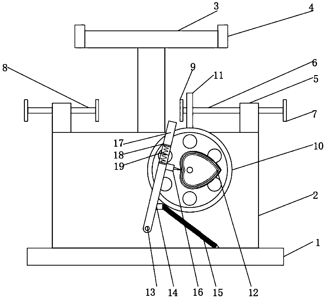
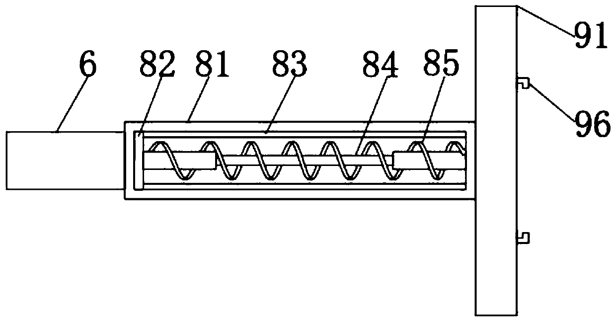
[0036] The adjustable rod 8 includes a hollow cylindrical rod 81, which is sleeved with a slide seat 82, and the upper and lower sides of the inner wall of the hollow cylindrical rod 81 are fixedly connected with slide rails 83, and the slide seat 82 slides on the two slide rails 83 , one side of the sliding seat 82 is elastically connected to one side of the inner wall of the hollow cylindrical rod 81;

[0037] When clamping the workpiece, first place one end of the workpiece on the clamping device 9 on the right side of the adjustable rod 8, move the workpiece to the left, and the clamping device 9 on the left side can move, so that when the right side of the workpiece and the right side The clamping device 9 is fixed after being contacted. This operation and installation process is simple, and under the action of elasticity, it can ensure the stability of workpiece clamping, and it can also be used for workpieces of different lengths, and the scope of use is wider.

Embodiment 2

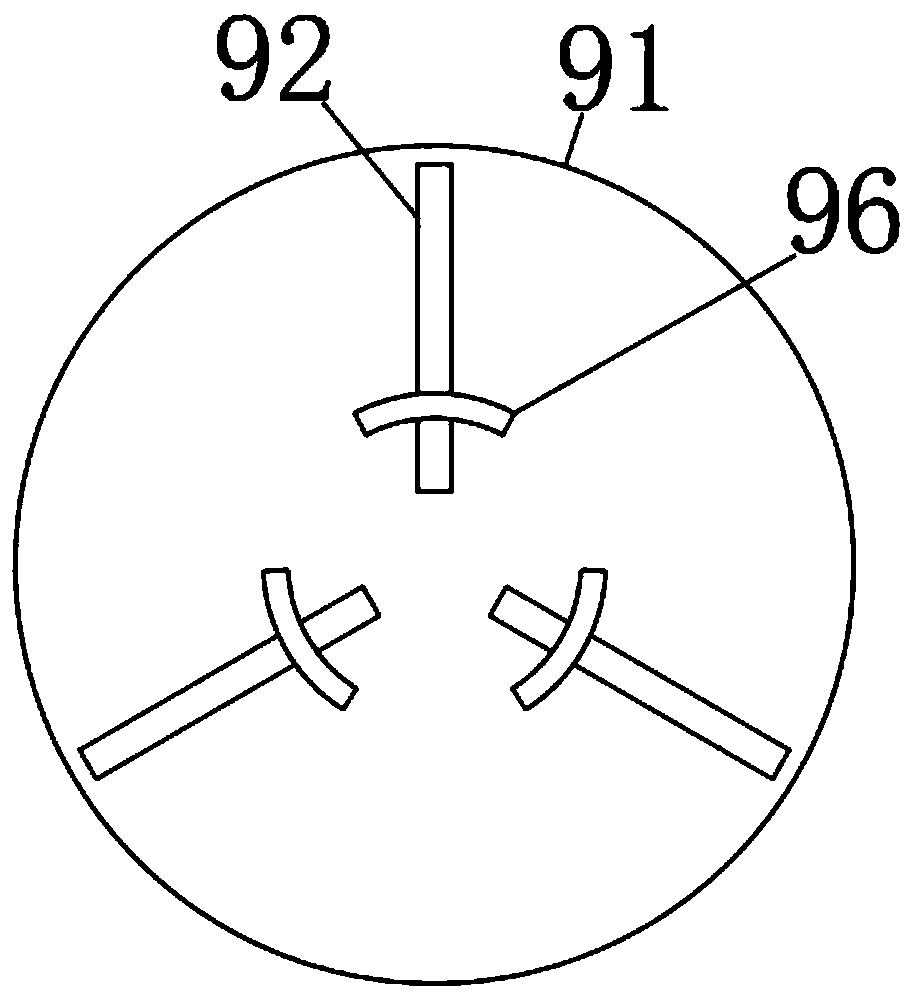
[0039] The clamping device 9 includes a clamping disc 91, one side of the clamping disc 91 is inlaid with three spring sleeves 92, the three spring sleeves 92 are equidistantly arranged, the angle between the intersection points of the extension lines of the three spring sleeves 92 is 120 degrees, and the spring sleeve 92 One side of the inner wall is elastically connected with a movable block 93, and one side of the movable block 93 is fixedly connected with an arc-shaped holder 96. When in use, the three arc-shaped holders 96 can clamp the workpiece tightly, thus ensuring the safety of the workpiece during winding. And stable, and according to the moving range of the arc-shaped clamping seat 96, it is also possible to increase the clamping of different workpieces.

[0040] In order to ensure that the winding rod 17 on the top of the swing rod 14 is in the winding process, along with the increase of the number of coils, the top of the winding rod 17 is prevented from contactin...


PUM


Abstract

The invention relates to the technical field of reciprocating coil winding devices, and discloses a reciprocating type coil winding device, which comprises a base, wherein a device shell is fixedly connected to the top of the base, a placing frame is fixedly connected to the middle of the front side of the top of the device shell, two placing seats are fixedly connected to the left side and the right side of the front face of the placing frame, and adjusting seats are fixedly connected to the left side and the right side of the top of the device shell. In the specific use process, when a heart-shaped disc drives a swing rod to move towards the left side, actually the heart-shaped disc rotates half a circle, and when the heart-shaped disc continuously rotates, a tension spring can enable the labor swing rod to quickly return to the state of moving rightwards, so that the stable winding is ensured; and a driving turbine is engaged with a driven turbine, and a driving device can drive a workpiece and the swing rod to rotate at the same time, so that the mechanical loss is reduced, the cost of a power supply is reduced, the device can be quickly operated by inexperienced people, and the employee can conveniently start the device.

Description

technical field [0001] The invention relates to the technical field of reciprocating coil winding devices, in particular to a reciprocating coil winding device. Background technique [0002] Coil winding machine: As the name suggests, a winding machine is a machine that winds a wire-like object onto a specific workpiece. Most electrical products need to be wound with enameled copper wire (referred to as enameled wire) to form an inductance coil, so a winding machine is required. [0003] During the winding operation of the existing winding machine, the winding workpiece is unstable when it is fixed, and the distance of the reciprocating path of the copper wire needs to be reciprocally controlled during the winding process. The existing factory uses a screw to push the worker to reciprocate When winding, when the copper wire is over-tensioned and loose when winding, the spacing of the winding will be affected, so that the early steps of winding will need to be repeated, and ...

Claims


Application Information

Patent Timeline
Patent Type & Authority Applications(China)
IPC IPC(8): H01F41/06H01F41/094
CPCH01F41/06H01F41/094
Inventor 陈昌宜康家文陈安宜康威
Owner 安徽聚益德电子科技有限公司
Why Eureka
Try Eureka