
A kind of spherical dielectric material and its production method and Lunberg lens

A technology of dielectric materials and production methods, applied in circuits, electrical components, antennas, etc., can solve problems such as easy separation of foamed materials and conductive fibers, low structural strength of dielectric materials, easy deformation of foamed materials, etc. The effect of light weight, low production cost, and accurate control of dielectric constant

Active Publication Date: 2021-12-14
CHINA UNITED NETWORK COMM GRP CO LTD +1
View PDF6 Cites 0 Cited by
  • Summary
  • Abstract
  • Description
  • Claims
  • Application Information

AI Technical Summary

Problems solved by technology

[0003] However, the products and manufacturing methods described in this publication are actually defective: due to the small size of the particles, usually only a few millimeters cubic, the sandwich structure formed by bonding is cut into granular dielectric material units At the same time, the foam material in the dielectric material unit is easily deformed, and the foam material and the conductive fiber are also easily separated after cutting, and the structural strength of the dielectric material is low.
In addition, this kind of production method of first overall production and then cutting requires a relatively large amount of cutting work in the later stage, and the requirements for cutting precision are also relatively high, which will eventually lead to an increase in production costs.

Method used


Image

  • A kind of spherical dielectric material and its production method and Lunberg lens
  • A kind of spherical dielectric material and its production method and Lunberg lens
  • A kind of spherical dielectric material and its production method and Lunberg lens

Examples


Embodiment 1

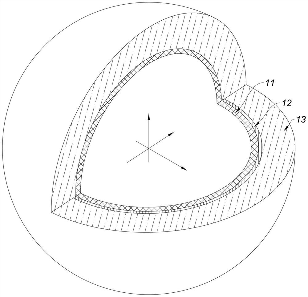
[0034] Such as figure 1 As shown, the present embodiment is a spherical dielectric material, which is a spherical structure, and the spherical structure includes an inner core 11, a conductive layer 12 and a foam material layer 13; the inner core 11 is made into a spherical shape, and the inner core The outer diameter of 11 is in the range of 3-6 mm, and the inner core 11 is made of non-metallic material; the conductive layer 12 is arranged on the surface of the inner core 11, and the area covered by the conductive layer 12 is equal to the inner core 11. Half of the outer surface area of ​​the core 11, the thickness of the conductive layer 12 is in the range of 0.01 to 0.5 mm; the outer surface of the foam material layer 13 is a spherical structure, and the inner surface of the foam material layer 13 wraps the conductive layer. The outer surface of the layer 12 and the part on the surface of the inner core 11 not covered by the conductive layer 12, the thickness of the foam ma...

Embodiment 2

[0038] This embodiment is a production method of a spherical dielectric material, which is characterized in that it includes the following production steps:

[0039] 1) Use non-metallic materials to produce a spherical inner core. The inner core in step 1) is made into a hollow structure. The inner core is specifically made of plastic or glass, and the outer diameter of the inner core is between 3 and Within the range of 6mm;

[0040]2) Spray conductive material on the outer surface of the inner core by a spraying device to form a conductive layer on the inner core. The area covered by the conductive layer on the outer surface of the inner core is equal to half of the outer surface area of ​​the inner core. The conductive layer in this step It is made into a hemispherical shape and the thickness of the conductive layer is in the range of 0.01-0.5mm; during production, the inner core is placed in the groove on the assembly line, and when the inner core on the assembly line walk...

Embodiment 3

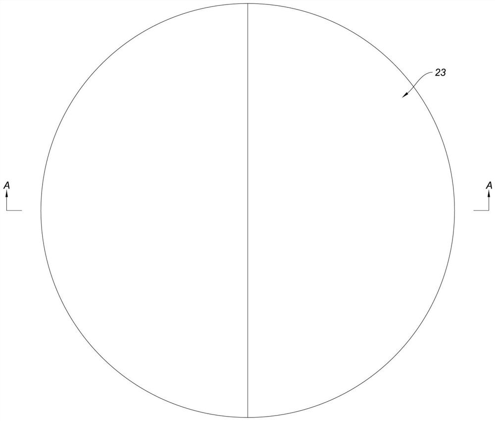
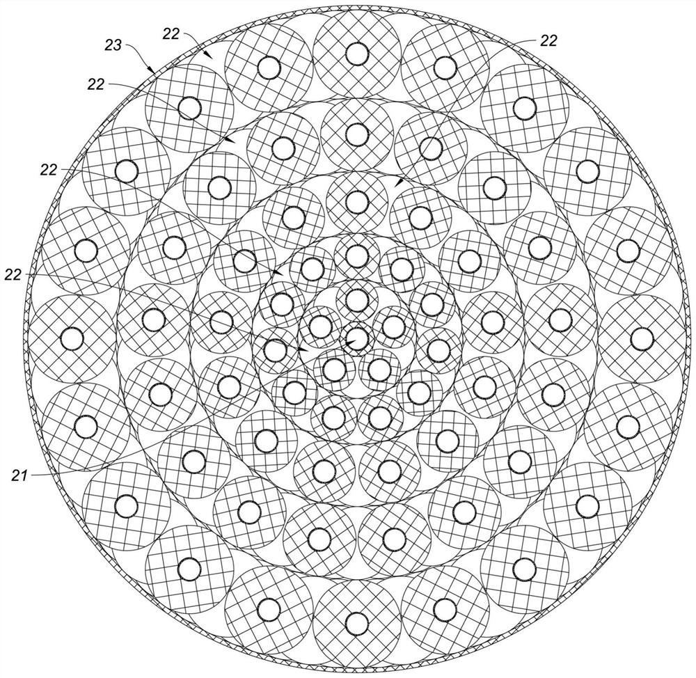
[0047] Such as figure 2 , image 3 As shown, the present embodiment is a Lunberg lens, comprising an inner core 21 and several dielectric layers 22 wrapping the inner core 21 layer by layer. In actual implementation, this Lunberg lens also includes a shell 23, an inner core 21 and a dielectric layer 22 It is in the shell 23; the inner core 21 is the spherical dielectric material described in Embodiment 1; each dielectric layer 22 is composed of several particle units respectively, and the particle units in each dielectric layer 22 are spherical dielectric materials described in Embodiment 1. Electrical material; the inner core 21 is connected with the dielectric layer 22 closest to the inner core 21 by glue, and the adjacent two dielectric layers 22 are also connected by glue; the inner core of the inner core 21 and each medium The inner core of the particle unit of layer 22 is identical, and the conductive layer of inner core 21 is identical with the conductive layer of the...


PUM

PropertyMeasurementUnit
diameteraaaaaaaaaa
thicknessaaaaaaaaaa
thicknessaaaaaaaaaa

Abstract

The invention relates to a spherical dielectric material, which is characterized in that it is a spherical structure, and the spherical structure includes an inner core, a conductive layer and a foam material layer; the inner core is made into a spherical shape, and the inner core is made of non-metallic material The conductive layer is arranged on the surface of the inner core, and the area covered by the conductive layer on the outer surface of the inner core is less than or equal to half of the outer surface area of ​​the inner core; the outer surface of the foam material layer is a spherical structure, and the foam The inner surface of the material layer wraps the outer surface of the conductive layer and the part of the surface of the inner core that is not covered by the conductive layer. The spherical dielectric material has the characteristics of simple structure, reasonable design, high structural strength, convenient processing and low production cost. The invention relates to a production method of a spherical dielectric material. The production method of the spherical dielectric material has the characteristics of high production efficiency, low cost, light weight and easy control of dielectric properties. The invention also relates to a Luneberg lens.

Description

technical field [0001] The invention relates to the technical field of dielectric materials, in particular to a spherical dielectric material; the invention also relates to a production method of the spherical dielectric material; and the invention also relates to a Lunberg lens. Background technique [0002] The patent document titled "AN ARTIFICIAL DIELECTRIC MATERIAL AND A METHOD OFMANUFACTURINGTHE SAME" with publication number WO2009078807 and published on June 25, 2009 discloses an artificial dielectric material and its manufacturing method. Can be used to make Lumber lenses. Its technical solution is mainly to put the long conductive fibers arranged in parallel between the upper and lower foam materials, and then cut the sandwich structure into granules after bonding and fixing, and the obtained granules contain short Conductive fibers that are not in contact with each other, these particles are randomly mixed and fixed together with a binder to obtain a dielectric ma...

Claims


Application Information

Patent Timeline
Patent Type & Authority Patents(China)
IPC IPC(8): H01Q13/28H01Q15/10H01P3/16
CPCH01Q13/28H01Q15/10H01P3/16
Inventor 张涛潘翔芦永超郑洪振
Owner CHINA UNITED NETWORK COMM GRP CO LTD
Learn More