Unlock instant, AI-driven research and patent intelligence for your innovation.

Stator-rotor double-permanent-magnet double-armature-winding magnetic field modulation permanent magnet motor structure

A double armature winding and armature winding technology, applied in the magnetic circuit shape/style/structure, electric components, magnetic circuit and other directions, can solve the problems of waste of space on the rotor side, poor reliability of torque output, and inability to generate torque. , to achieve the effect of improving torque density, high torque density, and strong fault tolerance.

Pending Publication Date: 2020-07-28
XI AN JIAOTONG UNIV
View PDF0 Cites 1 Cited by
  • Summary
  • Abstract
  • Description
  • Claims
  • Application Information

AI Technical Summary

Problems solved by technology

However, the existing field-modulated motors usually only include one set of armature windings (usually located on the stator), once the armature windings fail, they cannot generate torque, so the reliability of torque output is poor
On the other hand, in the existing topological structure of the field modulation motor, most of the rotor parts only contain permanent magnets or only use salient pole structure, resulting in waste of space on the rotor side

Method used


Image

  • Stator-rotor double-permanent-magnet double-armature-winding magnetic field modulation permanent magnet motor structure
  • Stator-rotor double-permanent-magnet double-armature-winding magnetic field modulation permanent magnet motor structure
  • Stator-rotor double-permanent-magnet double-armature-winding magnetic field modulation permanent magnet motor structure

Examples


Embodiment

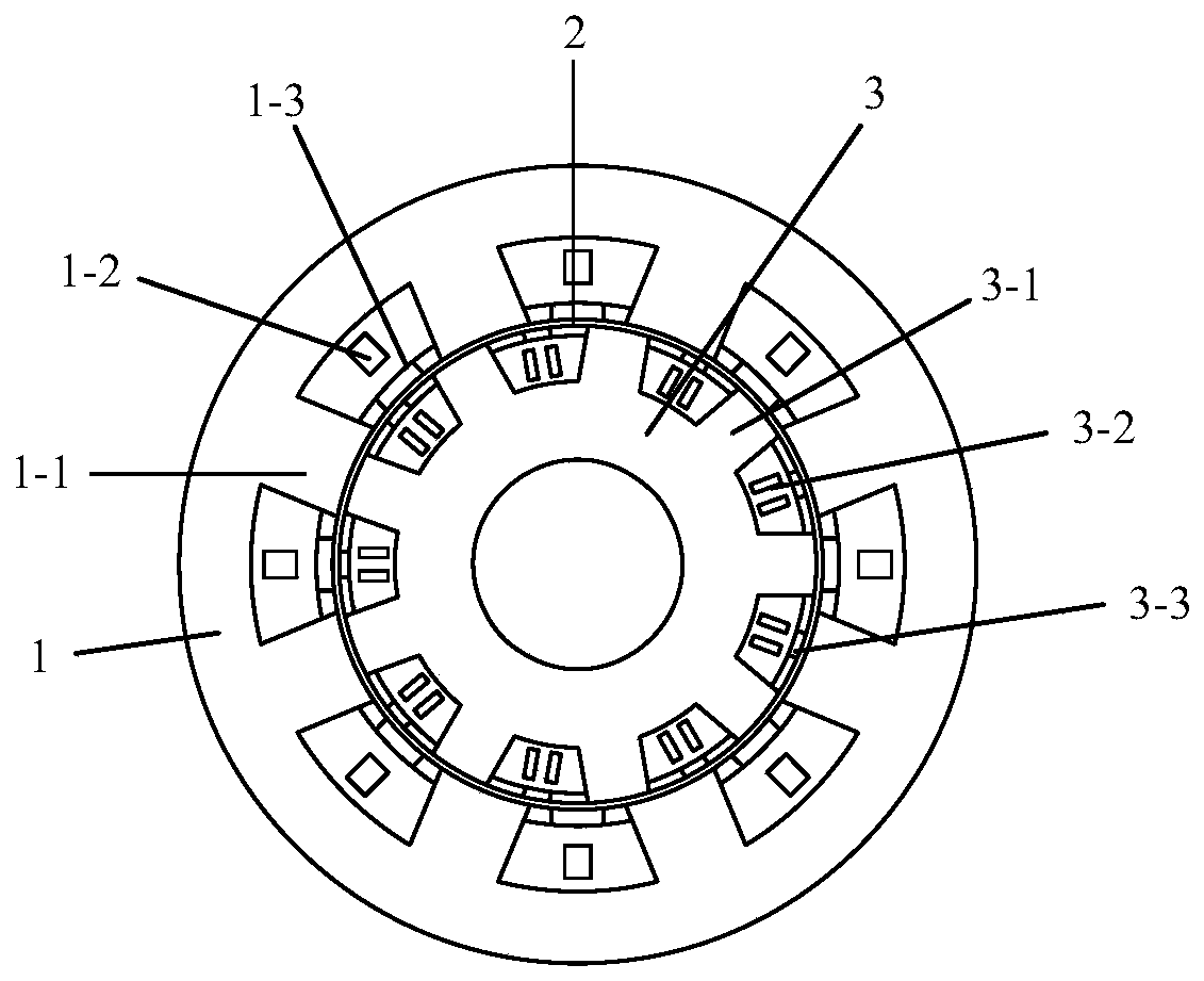
[0064] See figure 1 The present invention includes a stator 3, a rotor 1, an air gap 2 between the stator 3 and the rotor 1, the rotor 1 includes a rotor tooth 1-1, a rotor armature winding 1-2 and a rotor permanent magnet 1-3, and the stator 3 includes stator teeth 3-1. The stator armature winding 3-2 and the stator permanent magnet 3-3, the rotor armature winding 1-2 is wound on the rotor teeth 1-1 by two-phase armature winding, and the stator armature winding 3-2 is three The phase armature windings are wound on the stator teeth 3-1.

[0065] See figure 2 , figure 2 It is a star-shaped diagram of the stator winding of the present invention. The stator 3 of the present invention has 9 slots in total and adopts double-layer windings. The stator winding 3-2 is a three-phase distributed winding structure, which is fed with three-phase symmetrical alternating current to generate a pair of pole magnetic potential.

[0066] See image 3 , image 3 It is a star-shaped diagram of th...


PUM


Abstract

The invention discloses a stator and rotor double-permanent magnet double-armature winding magnetic field modulation permanent magnet motor, which comprises a stator and a rotor which are both of a salient pole structure, wherein the rotor and the stator rotate relatively, an annular air gap is formed between the stator and the rotor, the rotor comprises a rotor iron core, a rotor armature windingand a rotor permanent magnet, the rotor iron core comprises rotor teeth and a rotor yoke part, the rotor armature winding is wound on the rotor teeth by adopting a two-phase armature winding, the rotor permanent magnet is arranged in a groove between the two rotor teeth, the stator comprises a stator iron core, a stator armature winding and a stator permanent magnet, the stator iron core comprises stator teeth and a stator yoke part, the stator armature winding is wound on the stator teeth by adopting a three-phase armature winding, and the stator permanent magnet is arranged in a groove between the two stator teeth. The stator and rotor double-permanent magnet double-armature winding magnetic field modulation permanent magnet motor is of a double-salient-pole structure, adopts a magneticfield modulation principle, and is high in robustness, high in torque density and high in fault tolerance.

Description

Technical field [0001] The invention belongs to the field of motors, and particularly relates to a permanent magnet motor structure with stator and rotor double permanent magnets and double armature winding magnetic field modulation. Background technique [0002] In recent years, energy conservation and emission reduction have become the trend of the times, and new energy vehicles have become an important development direction for electric vehicles in the future. As the core power component of new energy vehicles, electric motors must have high torque density (power density), high efficiency and high fault tolerance. In addition, in the aerospace field, in order to reduce the weight of the motor, there are extremely high requirements for the power density of the motor. Due to the principle of magnetic field modulation, the magnetic field modulation motor has the characteristics of high torque density and has received more and more research and attention in the academic and indus...

Claims


Application Information

Patent Timeline
IPC IPC(8): H02K1/27H02K1/16H02K1/17
CPCH02K1/165H02K1/17H02K1/2786
Inventor 贾少锋冯帅梁得亮董晓壮诸自强刘进军
Owner XI AN JIAOTONG UNIV
Features
  • R&D
  • Intellectual Property
  • Life Sciences
  • Materials
  • Tech Scout
  • Unparalleled Data Quality
  • Higher Quality Content
  • 60% Fewer Hallucinations
Learn More