Stirring structure for microbial fertilizer

A technology of a microbial fertilizer and a stirring mechanism, which is applied in the field of microorganisms, can solve the problems of clogging, low stirring efficiency and affecting work efficiency, etc.

Inactive Publication Date: 2020-07-31
福建九州宇圣科技有限公司
View PDF7 Cites 8 Cited by
  • Summary
  • Abstract
  • Description
  • Claims
  • Application Information

AI Technical Summary

Problems solved by technology

[0003] However, the current stirring structure for microbial fertilizers is generally simple in structure. The microbial fertilizer is stirred by a single or multiple stirring shafts. The existing stirring structure for microbial fertilizers is not easy to stir the microbial fertilizer up and down, resulting in low stirring efficiency. And when transporting microbial fertilizers, blockages often occur, affecting work efficiency

Method used


Image

  • Stirring structure for microbial fertilizer
  • Stirring structure for microbial fertilizer
  • Stirring structure for microbial fertilizer

Examples


Embodiment 1

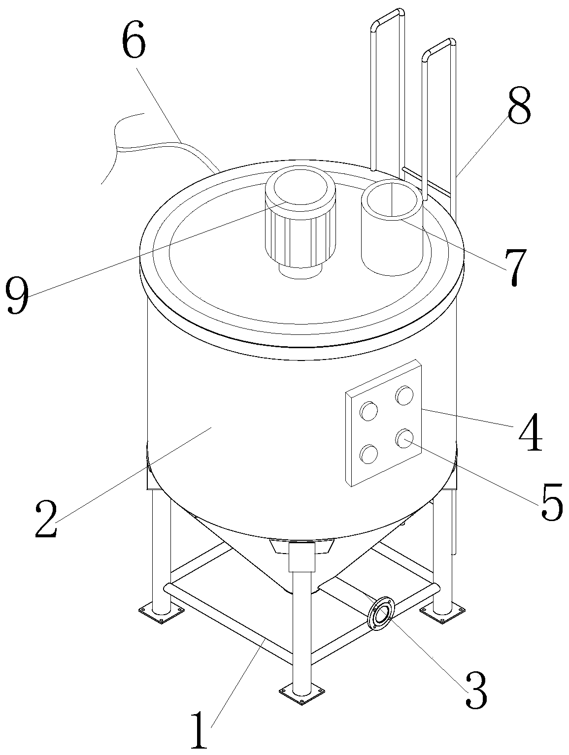
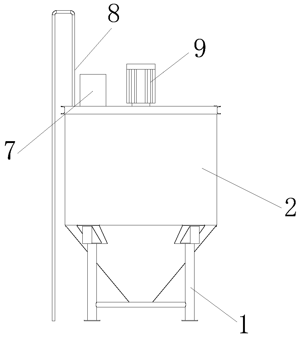
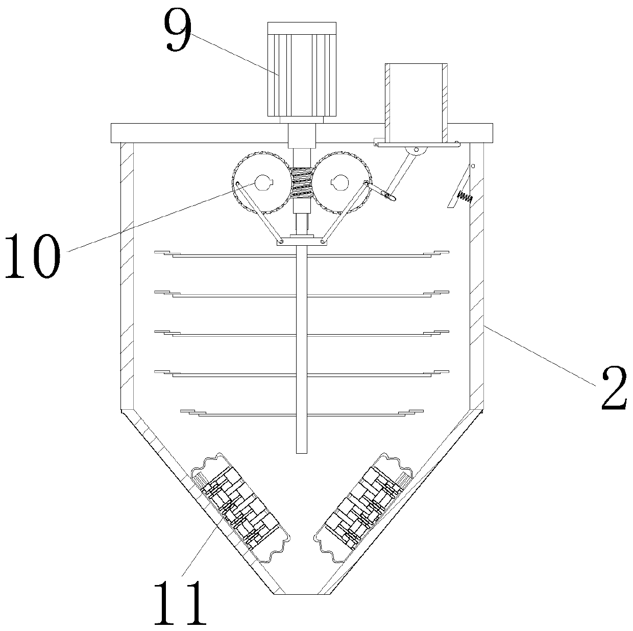
[0034] see figure 1 , figure 2 and image 3 , the present invention provides a kind of mixing structure that microbial fertilizer is used by improving here, comprises fixed frame 1, feeding hopper 7, escalator 8, first motor 9, lifting guide device 10 and auxiliary beating mechanism 11, and fixed frame 1 passes through Electric welding and the bottom of the stirring frame 2 are locked and fixed, the stirring frame 2 is connected to the left end of the discharge pipe 3, the right end of the stirring frame 2 is provided with a control panel 4, the front end of the control panel 4 is equipped with a button 5, and the lifting and deflecting device 10 is installed and fixed on the stirring frame 2. The inner upper end and the left end of the stirring frame 2 are fixed with a power wire 6. The stirring frame 2 is seamlessly connected with the bottom edge of the feeding hopper 7. The stirring frame 2 is fixedly connected to the front end of the escalator 8 by electric welding. The ...

Embodiment 2

[0041] The present invention provides a stirring structure for microbial fertilizers through improvement. The upper end of the first movable rod 1024 is provided with a chute 10241, and the second movable rod 1025 is slidably matched with the inner side of the chute 10241, and the upper end of the sealing plate 1021 is provided with a sealing protrusion. Block 10211, and the cross section of the sealing bump 10211 is semicircular, which is beneficial to play the role of sealing. The top of the beating head 117 is provided with a cushion pad 1171, and the cushion pad 1171 is seamlessly connected with the top of the beating head 117, which is conducive to buffering The upper end of the stirring shaft 1012 is provided with a sliding protrusion 10121, and there are two sliding protrusions 10121, which are located on the left and right sides of the upper end of the stirring shaft 1012, which is beneficial to make the stirring shaft 1012 rotate synchronously when lifting.

[0042] Th...


PUM


Abstract

The invention discloses a stirring structure for a microbial fertilizer. The stirring structure comprises a lifting guide device and an auxiliary beating mechanism; according to the invention, the lifting stirring mechanism is arranged in the stirring frame; the first motor drives the worm to rotate; the worm drives the stirring shaft to rotate; meanwhile, a worm rotates to drive a first worm wheel and a second worm wheel to rotate, so that the first worm wheel and the second worm wheel drive a fixed seat and a stirring shaft to move up and down through a first swing rod and a second swing rodat the upper ends, and the advantages of up-and-down reciprocating stirring of the microbial fertilizer and uniform mixing are achieved; an auxiliary beating mechanism is arranged in the stirring frame; the second motor drives the rotating shaft to rotate, so that the rotating shaft drives the crank to swing through the rotating piece, the crank drives the beating head to beat the telescopic protective cover in a reciprocating mode, the telescopic protective cover vibrates and flies fertilizer at the upper end for further mixing, and the advantage that the fertilizer mixing efficiency can beimproved is achieved.

Description

technical field [0001] The invention relates to the field of microorganisms, in particular to a stirring structure for microbial fertilizers. Background technique [0002] Microbial fertilizers contain a large number of beneficial microorganisms, which can improve crop nutritional conditions, fix nitrogen and activate some ineffective nutrient elements in the soil, create a good soil micro-ecological environment to promote crop growth, and beneficial microorganisms in microbial fertilizers can produce carbohydrates , accounting for 0.1% of soil organic matter, combined with plant mucus, mineral embryo bodies and organic colloids, can improve the soil aggregate structure, enhance the physical properties of the soil and reduce the loss of soil particles. Under certain conditions, it can also participate in humus form. [0003] However, the current stirring structure for microbial fertilizers is generally simple in structure. The microbial fertilizer is stirred by a single or ...

Claims


Application Information

Patent Timeline
Patent Type & Authority Applications(China)
IPC IPC(8): B01F7/16B01F7/18B01F11/00B01F15/00B01F15/02
CPCB01F27/806B01F31/441B01F2035/3513B01F27/90B01F35/31B01F35/3204B01F35/716B01F2101/32
Inventor 陈佳莲
Owner 福建九州宇圣科技有限公司
Why Eureka
Try Eureka