
Building broken excess material deironing device

A technology of residual materials and construction, applied in the direction of magnetic separation, solid separation, chemical instruments and methods, etc., can solve the problem of low removal rate of iron impurities, achieve the effect of improving the removal rate of iron impurities and improving the quality

Inactive Publication Date: 2020-07-31
陕西盛泰浩景建材有限公司
View PDF6 Cites 8 Cited by
  • Summary
  • Abstract
  • Description
  • Claims
  • Application Information

AI Technical Summary

Problems solved by technology

[0004] The above-mentioned existing technical solution has the following defects: if the above-mentioned patent is used to remove iron from the recycled aggregate, the recycled aggregate will be transported along with the conveyor belt, and the iron impurities in it will be attracted and removed by the magnet. However, since the recycled aggregate is easy to pile up from The feeding cylinder is discharged to the conveyor belt. During the conveying process, the iron impurities inside the recycled aggregate are also difficult to be attracted by the magnet, resulting in a low removal rate of iron impurities.

Method used


Image

  • Building broken excess material deironing device
  • Building broken excess material deironing device
  • Building broken excess material deironing device

Examples


Embodiment Construction

[0036] The present invention will be described in further detail below in conjunction with the accompanying drawings.

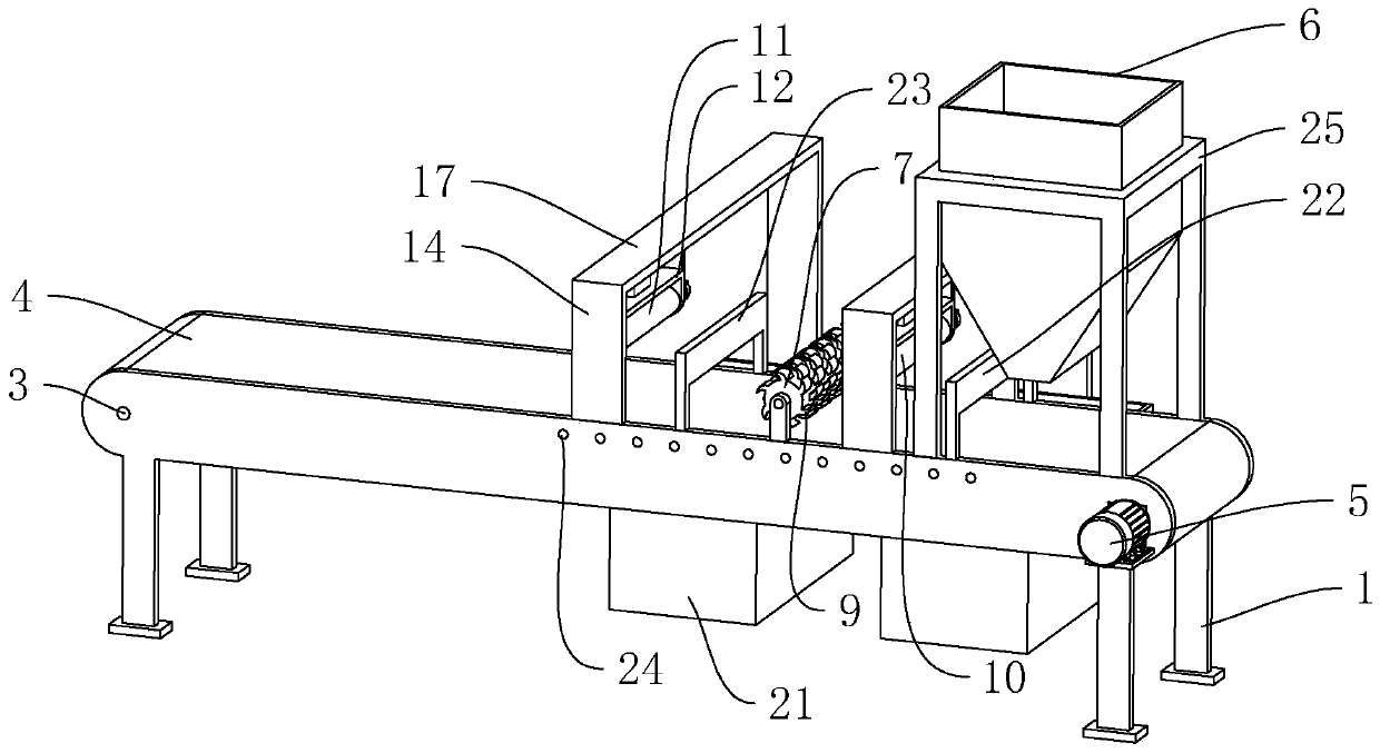
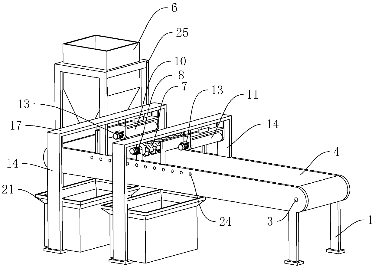
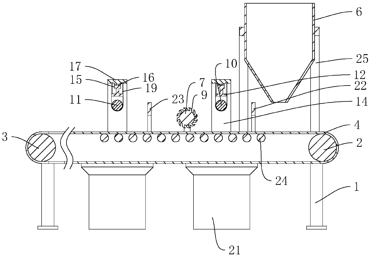
[0037] refer to figure 1 and figure 2 , which is a device for removing iron from building crushing leftovers disclosed in the present invention, comprising a rectangular parallelepiped frame 1 as a whole, and driving rollers 2 are respectively connected to the two ends of the frame 1 (refer to image 3 ) and the driven roller 3, the driving roller 2 and the driven roller 3 are surrounded by a conveyor belt 4, and the frame 1 is provided with a driving assembly that drives the driving roller 2 to rotate. In this embodiment, the driving assembly is a driving motor 5 , the body of the driving motor 5 is fixedly connected with the frame 1 by bolts, the rotating shaft of the driving motor 5 is coaxial and fixedly connected with the driving roller 2, a feeding hopper 6 is arranged above the feeding end of the conveyor belt 4, and the frame 1 is connected by bolts...


PUM


Abstract

The invention discloses a building broken excess material deironing device, and relates to the technical field of building excess material regeneration. According to the technical key points, the device comprises a rack; a driving roller and a driven roller are rotationally connected with the two ends of the rack correspondingly; a conveying belt is wound on the peripheral sides of the driving roller and the driven roller; a driving assembly for driving the driving roller to rotate is arranged on the rack; a feeding hopper is arranged above the feeding end of the conveying belt; a material overturning roller is horizontally arranged on the side, away from the feeding end, of the feeding hopper; the material overturning roller is located above the conveying belt and is perpendicular to themoving direction of the conveying belt; a rotating assembly for driving the material overturning roller to rotate is arranged on the rack; a plurality of arc-shaped material overturning teeth are anticlockwise arranged on the circumferential side of the material overturning roller in the circumferential direction, and concave faces of the material overturning teeth face the circumferential side ofthe material overturning roller; a first electromagnetic deironing roller parallel to the axis of the material overturning roller is arranged between the material overturning roller and the outlet ofthe feeding hopper; and a second electromagnetic deironing roller parallel to the axis of the material overturning roller is arranged on the side, away from the feeding hopper, of the material overturning roller. The device has the advantage of improving the iron impurity removal rate of the recycled aggregate.

Description

technical field [0001] The invention relates to the technical field of regeneration of construction waste materials, in particular to a device for removing iron from construction waste materials. Background technique [0002] In recent years, due to the rapid development of real estate, the civil engineering and building materials industry has become increasingly prosperous. In the process of building construction, concrete materials are indispensable. Construction waste, also known as construction waste, mainly consists of concrete, bricks, sand, gravel, and muck. In the process of urban construction and old city renovation, a large amount of construction waste and construction waste will be generated, and its amount has accounted for the total amount of urban waste. 30%-40% of this problem can be well solved, which is related to the major livelihood issues of various cities in various countries, such as cultivated land protection, environmental protection, quality of life,...

Claims


Application Information

Patent Timeline
Patent Type & Authority Applications(China)
IPC IPC(8): B03C1/26B03C1/18
CPCB03C1/18B03C1/26
Inventor 肖锋兴
Owner 陕西盛泰浩景建材有限公司
Learn More