Steel rail accumulated snow removing robot

A robot and snow accumulation technology, applied in snow surface cleaning, construction, cleaning methods, etc., can solve the problem of not being able to push the snow away from the rails, and achieve the effect of improving the quality of snow removal, increasing the speed of snow removal, and preventing snow piles from collapsing

Inactive Publication Date: 2021-06-11
陈波浪
View PDF1 Cites 1 Cited by
  • Summary
  • Abstract
  • Description
  • Claims
  • Application Information

AI Technical Summary

Problems solved by technology

[0002] For example, the publication CN110528450A includes a main body, and the right side of the main body is provided with a snow removal device for collecting snow accumulated in the track. A snow shovel, the lower ends of the front and rear end surfaces of the snow shovel are rotatably connected to the front and rear walls of the turning chamber, the snow shovel is provided with a conveying chamber that penetrates up and down and opens to the left, and the front and rear walls of the conveying chamber are vertically symmetrical And rotatably be provided with conveying wheel, be equipped with conveying belt around between described conveying wheel; The shortcoming of this invention is that snow can't be pushed far away from rail

Method used


Image

  • Steel rail accumulated snow removing robot
  • Steel rail accumulated snow removing robot
  • Steel rail accumulated snow removing robot

Examples


specific Embodiment approach 1

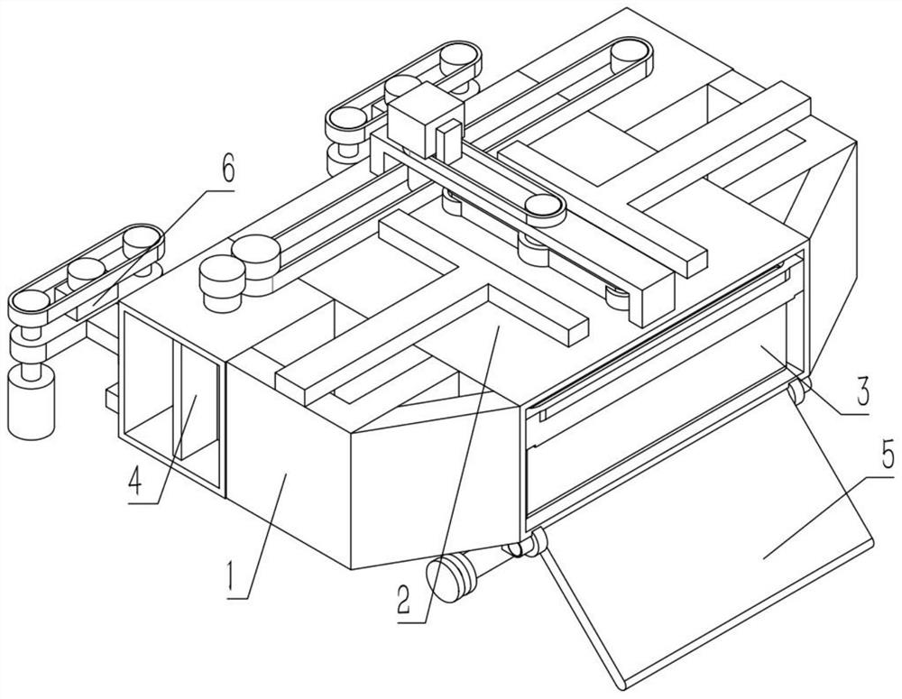
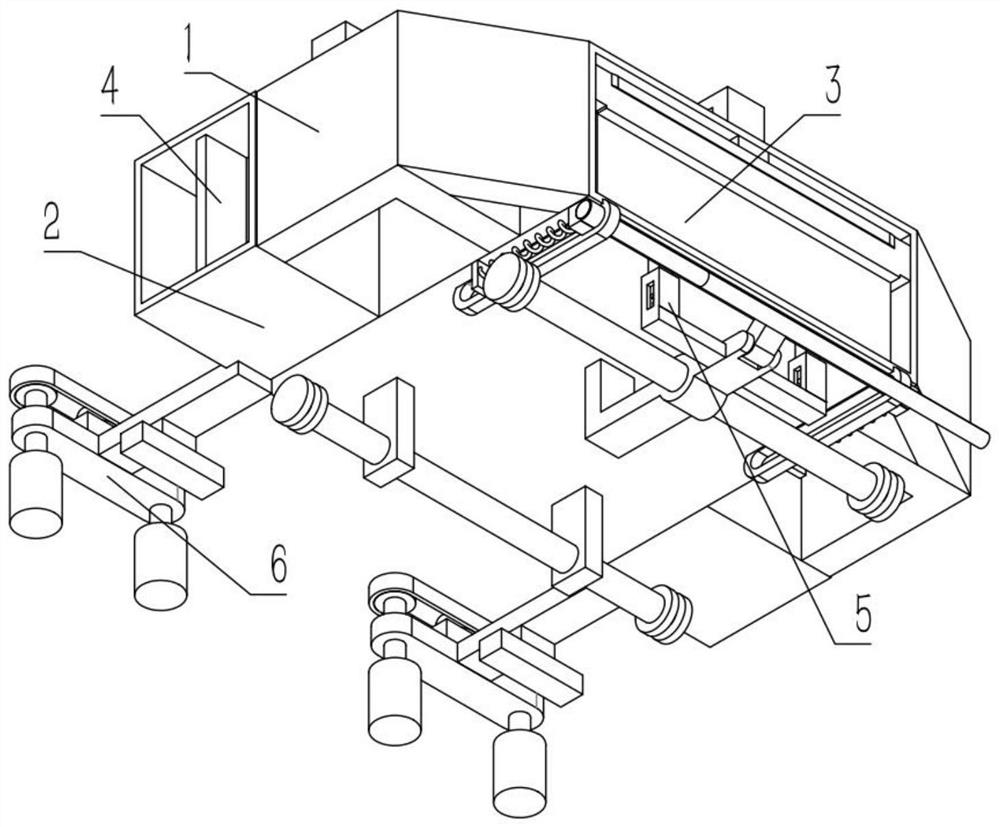
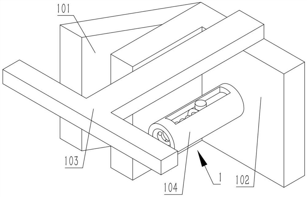
[0032] Combine below Figure 1-8 Describe this embodiment, a rail snow removal robot, including a snow pushing mechanism 1 and a collection mechanism 2, the snow pushing mechanism 1 includes a snow pushing slant 101, a snow pushing plate 102, a snow pushing slide bar 103 and a snow pushing Sleeve 104, snow push plate 102 is slidably connected on the snow push slant plate 101, is provided with a slide bar on the snow push plate 102, and snow push plate 102 is slidably connected in the snow push sleeve 104, pushes snow push plate 102 is fixedly connected to the lower end of the snow pushing rod 103, and the collection mechanism 2 includes a snow pushing rotating rod 201 and a snow pushing runner 202, and the two snow pushing runners 202 are connected to the front and rear ends of the snow pushing rotating rod 201 in rotation respectively. Each snow-pushing runner 202 is frictionally driven between the two snow-pushing slide bars 103;

[0033] When the device cleans the snow on ...

specific Embodiment approach 2

[0035] Combine below Figure 1-8 Describe this embodiment, this embodiment will further explain Embodiment 1, the collection mechanism 2 also includes a collection pulley shaft 203, a collection body 204, a collection chute 205 and a collection fixing rod 206, and the collection pulley shaft 203 is rotatably connected to the collection body 204, two collection chutes 205 are respectively fixedly connected to the left and right ends of the collection body 204, the collection fixed rod 206 is fixedly connected to the lower end of the collection body 204, and the two snow pushing ramps 101 are respectively fixedly connected to the collection body 204. At the left and right ends, the two snow pushing plates 102 are connected to the collecting main body 204 by springs, the two snow pushing slide rods 103 are slidably connected to the upper end of the collecting main body 204, and the snow pushing rotating rod 201 is fixedly connected to the collecting pulley shaft 203 ;

[0036] The...

specific Embodiment approach 3

[0038] Combine below Figure 1-8 Illustrate this embodiment, and this embodiment will further illustrate the second embodiment. The rail snow removal robot also includes a snow gathering mechanism 3, and the snow gathering mechanism 3 includes a snow gathering rotating rod 301, a snow gathering carriage 302 and a snow gathering mechanism. Snow turning plate 303 is provided with a chute on the snow gathering carriage 302, and a limit plate is provided on the snow gathering carriage 302. The plate 303 is rotatably connected to the lower end of the snow gathering carriage 302, the snow gathering rotating plate 303 and the snow gathering carriage 302 are connected by a torsion spring, the snow gathering rotating rod 301 is fixedly connected to the lower end of the collection pulley shaft 203, and the snow gathering rotating rod 301 rotates Connected to the collection body 204, the snow collecting carriage 302 is slidably connected to the collection body 204;

[0039] The collecti...


PUM


Abstract

The invention relates to the technical field of steel rail accumulated snow removal, in particular to a steel rail accumulated snow removing robot which comprises a snow pushing mechanism and a collecting mechanism, the snow pushing mechanism comprises a snow pushing inclined plate, a snow pushing plate, a snow pushing sliding rod and a snow pushing sleeve, the snow pushing plate is slidably connected to the snow pushing inclined plate, and a sliding rod is arranged on the snow pushing plate. The snow pushing plate is slidably connected into the snow pushing sleeve, the snow pushing plate is fixedly connected to the lower end of the snow pushing sliding rod, the collecting mechanism comprises a snow pushing rotating rod and snow pushing rotating wheels, the two snow pushing rotating wheels are rotationally connected to the front end and the rear end of the snow pushing rotating rod respectively, and the two snow pushing rotating wheels are in friction transmission with the two snow pushing sliding rods. When the steel rail accumulated snow removing robot removes the snow on the steel rail, the cleaned snow can be pushed away from the steel rail, so that the steel rail is prevented from being covered again by collapse of snow piles.

Description

technical field [0001] The invention relates to the technical field of rail snow removal, in particular to a rail snow removal robot. Background technique [0002] For example, the publication CN110528450A includes a main body, and the right side of the main body is provided with a snow removal device for collecting snow accumulated in the track. A snow shovel, the lower ends of the front and rear end surfaces of the snow shovel are rotatably connected to the front and rear walls of the turning chamber, the snow shovel is provided with a conveying chamber that penetrates up and down and opens to the left, and the front and rear walls of the conveying chamber are vertically symmetrical And rotatably be provided with conveying wheel, be equipped with conveying belt around between described conveying wheel; The shortcoming of this invention is that snow can't be pushed far away from steel rail. Contents of the invention [0003] The object of the present invention is to prov...

Claims


Application Information

Patent Timeline
Patent Type & Authority Applications(China)
IPC IPC(8): E01H5/08
CPCE01H5/08
Inventor 陈波浪
Owner 陈波浪
Why Eureka
Try Eureka