Automatic blow molding machine adopting artificialized feeding and discharging

An automatic blow molding, feeding and discharging technology, which is applied in the field of automatic blow molding machines, can solve the problems of air leakage, affecting the efficiency and effect of blow molding production, and prolonging the time required for blow molding, so as to achieve safe and convenient use and reduce the cost of pumps. Gas time, increase efficiency effect

Inactive Publication Date: 2020-07-31
张周钦
View PDF6 Cites 5 Cited by
  • Summary
  • Abstract
  • Description
  • Claims
  • Application Information

AI Technical Summary

Problems solved by technology

[0004] The present invention provides a technical solution, which can effectively solve the problem that when the tubular plastic parison is blow-molded in the above-mentioned background technology, since there are gaps between the tubular plastic parison molds, it is easy to cause the air passing into the tubular plastic parison to leak out, resulting in The time required for blow molding is prolonged, which affects the efficiency and effect of blow molding production

Method used


Image

  • Automatic blow molding machine adopting artificialized feeding and discharging
  • Automatic blow molding machine adopting artificialized feeding and discharging
  • Automatic blow molding machine adopting artificialized feeding and discharging

Examples


Embodiment

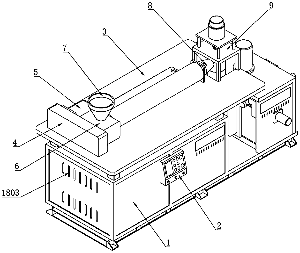
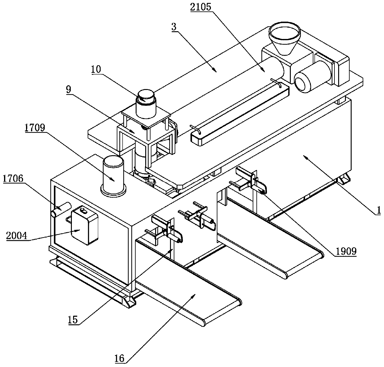
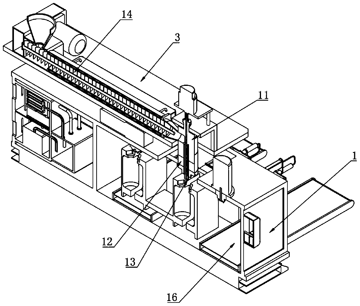
[0057] Example: such as Figure 1-15 As shown, the present invention provides a technical solution, a kind of manual automatic blow molding machine for feeding and discharging materials, including a blow molding machine box 1, a control switch 2 is installed at one end of the blow molding machine box 1, and the top of the blow molding machine box 1 is installed through a connecting column There is a top plate 3, the top of the top plate 3 is fixedly connected with a transmission chamber 4, the top of the top plate 3 is connected to an injection motor 5 at one end of the transmission chamber 4, and a hot melt chamber is installed at one end of the transmission chamber 4 corresponding to the side of the injection motor 5 6. The top of the hot-melt bin 6 is fixedly connected with the feeding bin 7, and one end of the hot-melt bin 6 is fixedly installed with a feeding pipe 8, and the top of the top plate 3 is connected with a placement frame 9 at a position above the feeding pipe 8...


PUM


Abstract

The invention discloses an automatic blow molding machine adopting artificialized feeding and discharging. The automatic blow molding machine adopting artificialized feeding and discharging comprisesa blow molding machine box. One end of the blow molding machine box is provided with a control switch. The top end of the blow molding machine box is provided with an top plate through connection columns. The top end of the top plate is fixedly connected with a transmission bin, and the end, corresponding to the transmission bin, of the top end of the top plate is connected with an injection molding motor. The side, corresponding to the injection molding motor, of one end of the transmission bin is provided with a hot melting bin. The automatic blow molding machine adopting artificialized feeding and discharging is scientific and reasonable in structure and safe and convenient to use. By arranging a first hydraulic lever, a first side mold, a shifting side mold and a second side mold, theefficiency of the blow molding process is improved, through combination with arrangement of a six-edge seal ring and a six-edge seal groove, the seal performance during blow molding can be improved, and the air pumping time required during blow molding is shortened; by arranging a draw-off pump, an absorption bin, a transfer pipe, a dispersion plate, activated carbon plates and a desiccant plate,absorption of harmful gas in air is convenient during blow molding of raw materials, and the safety guarantee during blow molding production is improved.

Description

technical field [0001] The invention relates to the technical field of automatic blow molding machines, in particular to a manual automatic blow molding machine for feeding and discharging materials. Background technique [0002] The blow molding machine is a kind of plastic processing machine. The tubular plastic parison obtained by extrusion or injection molding of thermoplastic resin is placed in the split mold while it is hot. After the mold is closed, compressed air is injected into the parison to make the plastic The parison is inflated and clings to the inner wall of the mold, and after cooling and demoulding, various hollow products can be obtained; [0003] At present, when the existing automatic blow molding machines on the market are used, when the tubular plastic parison is blown, because there are gaps between the tubular plastic parison molds, it is easy to cause the air passing into the tubular plastic parison to leak out, resulting in blow molding. The time ...

Claims


Application Information

Patent Timeline
Patent Type & Authority Applications(China)
IPC IPC(8): B29C49/28B29C49/50B29C49/56B29C49/64B29C49/42
CPCB29C49/28B29C49/50B29C49/56B29C49/64B29C49/42B29C49/4278B29C49/4284B29C2049/4294B29C49/28012
Inventor 张周钦
Owner 张周钦
Why Eureka
Try Eureka