Integrated three-stage speed reduction electric drive axle

A three-stage deceleration and electric drive technology, which is applied to axles, wheels, control devices, etc., can solve the problems of large vehicle matching space requirements, large drive axle volume, and low integration, and achieve good vehicle adaptability, The effect of light weight of the motor and simple assembly process

Pending Publication Date: 2020-07-31
GUANGXI YUCHAI MASCH CO LTD
View PDF5 Cites 4 Cited by
  • Summary
  • Abstract
  • Description
  • Claims
  • Application Information

AI Technical Summary

Problems solved by technology

The structure is a three-stage deceleration electric drive axle, which can achieve a large speed ratio reduction, but there are still some shortcomings in this structure. Although this structure only integrates the three-stage reducer, and the differential is set inside the axle housing, but The integration level is still not high, and the motor casing, differential casing and reducer casing still need to be installed and connected, and the structure is complex, resulting in a large volume of the drive axle, a large space requirement for matching with the whole vehicle, and poor adaptability it is good

Method used


Image

  • Integrated three-stage speed reduction electric drive axle
  • Integrated three-stage speed reduction electric drive axle

Examples


Embodiment 1

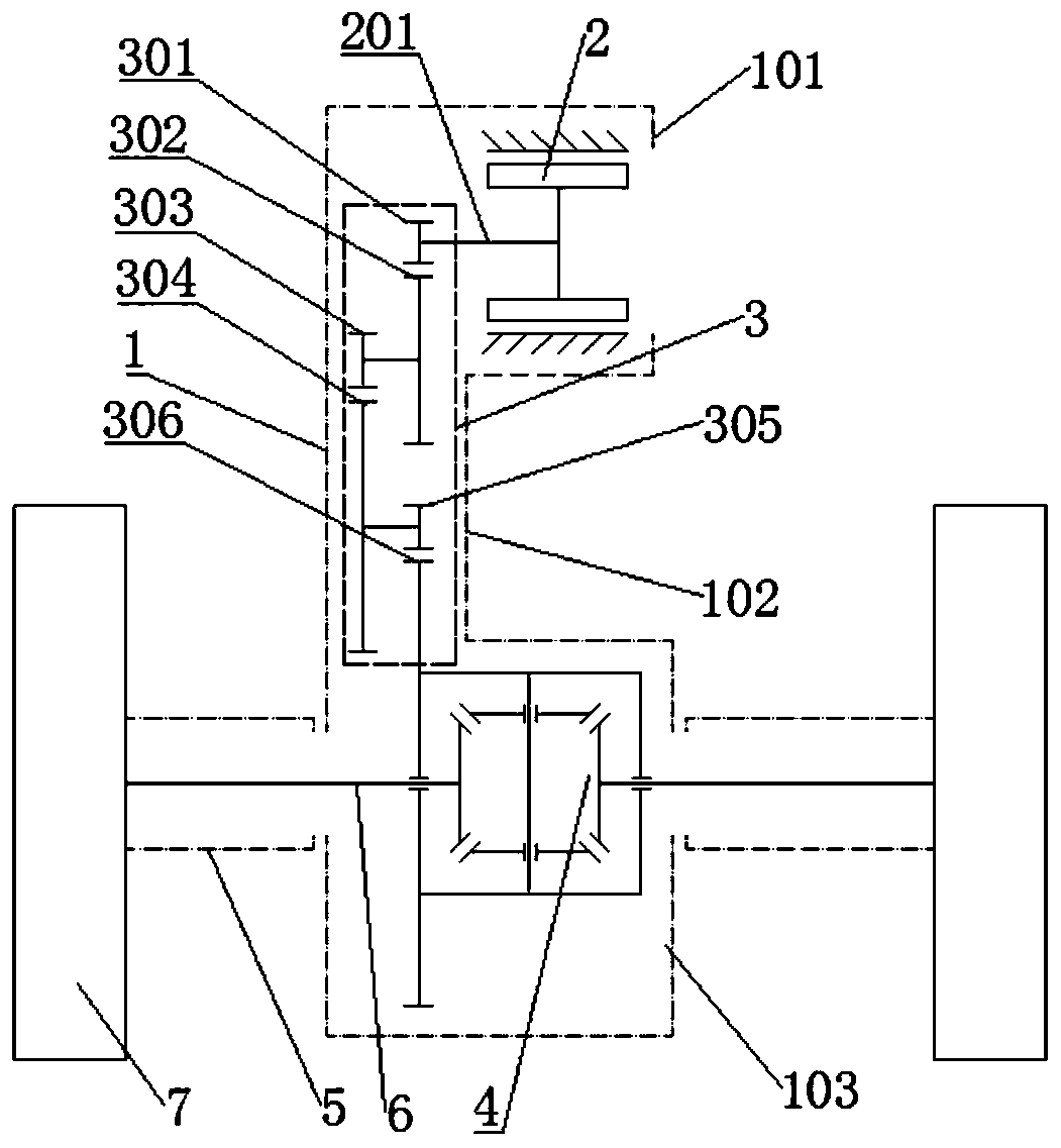
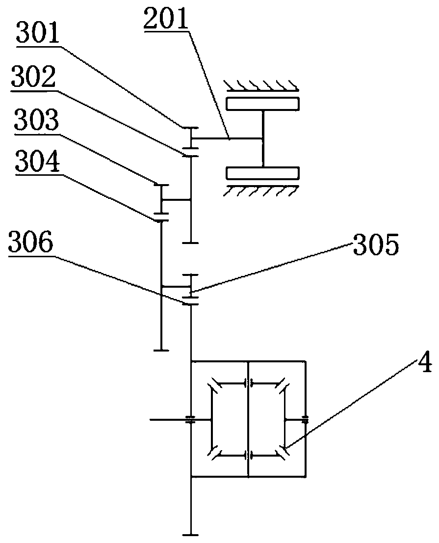
[0021] Such as figure 1 As shown, an integrated three-stage deceleration electric drive axle includes an integrated housing 1, and the integrated housing 1 is provided with a motor 2, a three-stage parallel reduction gear set 3 and a differential 4 that are sequentially connected in transmission. The integrated housing 1 is integrally formed; it also includes an axle housing 5, an axle shaft 6 and a wheel 7. The axle housing 5 is connected to the vehicle frame and is located on both sides of the integrated housing 1. The axle shaft 6 is set Inside the axle housing 5 , one end of the axle shaft 6 is connected to the output end of the differential 4 and the other end is connected to the wheel 7 .

[0022] The working principle of this embodiment is as follows:

[0023] Power transmission path: the power is output by the motor 2, after the deceleration and torque increase of the three-stage parallel reduction gear set 3, the power is transmitted to the half shafts 6 on the left ...

Embodiment 2

[0025] Such as figure 1 As shown, an integrated three-stage deceleration electric drive axle includes an integrated housing 1, and the integrated housing 1 is provided with a motor 2, a three-stage parallel reduction gear set 3 and a differential 4 that are sequentially connected in transmission. The integrated housing 1 is an integral casting structure, that is, the integrated housing 1 integrates the motor housing 101, the reducer housing 102 and the differential housing 103; it also includes the axle housing 5, the axle shaft 6 and the wheels 7, and the axle housing 5. The axle shafts 6 and the wheels 7 are arranged in pairs on both sides of the differential 4. The integrated housing 1 is used as the middle part of the axle, and is respectively connected with the axle housing 5 on the left and the axle housing 5 on the right. The housing 5 is connected to the vehicle frame and located on both sides of the integrated housing 1, the axle shaft 6 is arranged inside the axle ho...


PUM


Abstract

The invention relates to the technical field of electric vehicles, and particularly relates to an integrated three-stage speed reduction electric drive axle. The integrated three-stage speed reductionelectric drive axle comprises an integrated shell, wherein the integrated shell is internally provided with a motor, a three-stage parallel speed reduction gear set and a differential mechanism whichare in transmission connection in sequence, and the integrated shell is of an integrally-formed structure. The integrated three-stage speed reduction electric drive axle further comprises an axle housing, a half shaft and wheels, wherein the two sides of the integrated shell are connected with the axle housing, the half shaft is arranged in the axle housing, one end of the half shaft is connectedwith the output end of the differential mechanism, and the other end of the half shaft is connected with the wheels. The system is high in integration degree, compact in structure and small in occupied space, a transmission shaft is not needed, a battery pack can be arranged in the middle of a vehicle girder, the adaptability to the complete vehicle is good, and the assembling process is simple.

Description

technical field [0001] The invention relates to the technical field of electric vehicles, in particular to an integrated three-stage reduction electric drive axle. Background technique [0002] With the depletion of oil resources and the intensification of air pollution, pure electric vehicles are the future development direction of automobiles that can alleviate energy and environmental problems. More and more scientific research institutions, universities and enterprises have increased their investment in the research of pure electric vehicles. , the new pure electric vehicles mainly use electric drive. Compared with traditional internal combustion engine drive, electric drive has many advantages, such as vehicle structure layout, stepless speed change, improved vehicle power performance and economic performance, but due to the limitation of motor and its control technology However, pure electric vehicles cannot maximize their advantages, and problems such as an excessivel...

Claims


Application Information

Patent Timeline
Patent Type & Authority Applications(China)
IPC IPC(8): B60B35/12B60B35/14B60B35/16B60K17/12B60K17/16
CPCB60B35/125B60B35/14B60B35/16B60K17/12B60K17/165
Inventor 林志强毛正松张松吴苾曜陈涛高阿鹏陆浩欧阳石坤谭长珅邓玉胜刘健华翚祎萌刘兵梁健麟杨奕曾敏赵宏辑陆祖汉
Owner GUANGXI YUCHAI MASCH CO LTD
Why Eureka
Try Eureka