

Steam device and operation and use method thereof
A steam generator and steam technology, applied in applications, current collectors, electric vehicles, etc., can solve the problems of limited power cord length and limited use range, and achieve the effect of eliminating potential safety hazards and reducing labor intensity.
- Summary
- Abstract
- Description
- Claims
- Application Information
AI Technical Summary
Problems solved by technology
Method used
Image

Examples
Embodiment 2
[0088] An operation and use method is applied to the steam appliance in the first embodiment. The method comprises the following steps:
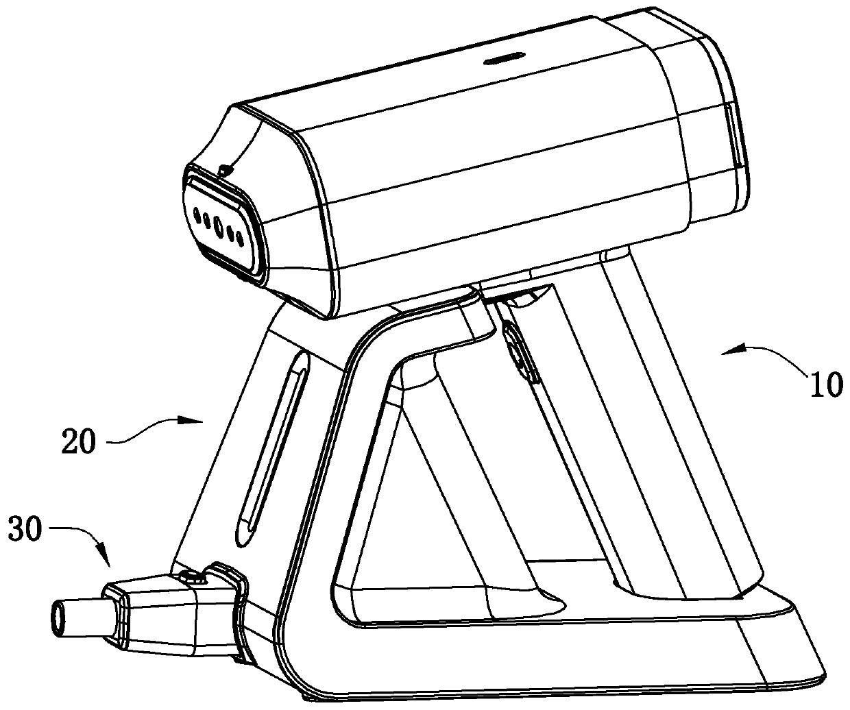
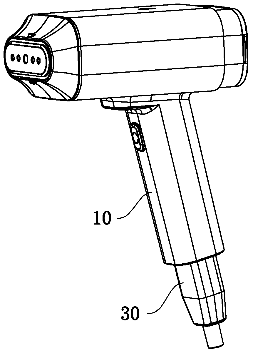
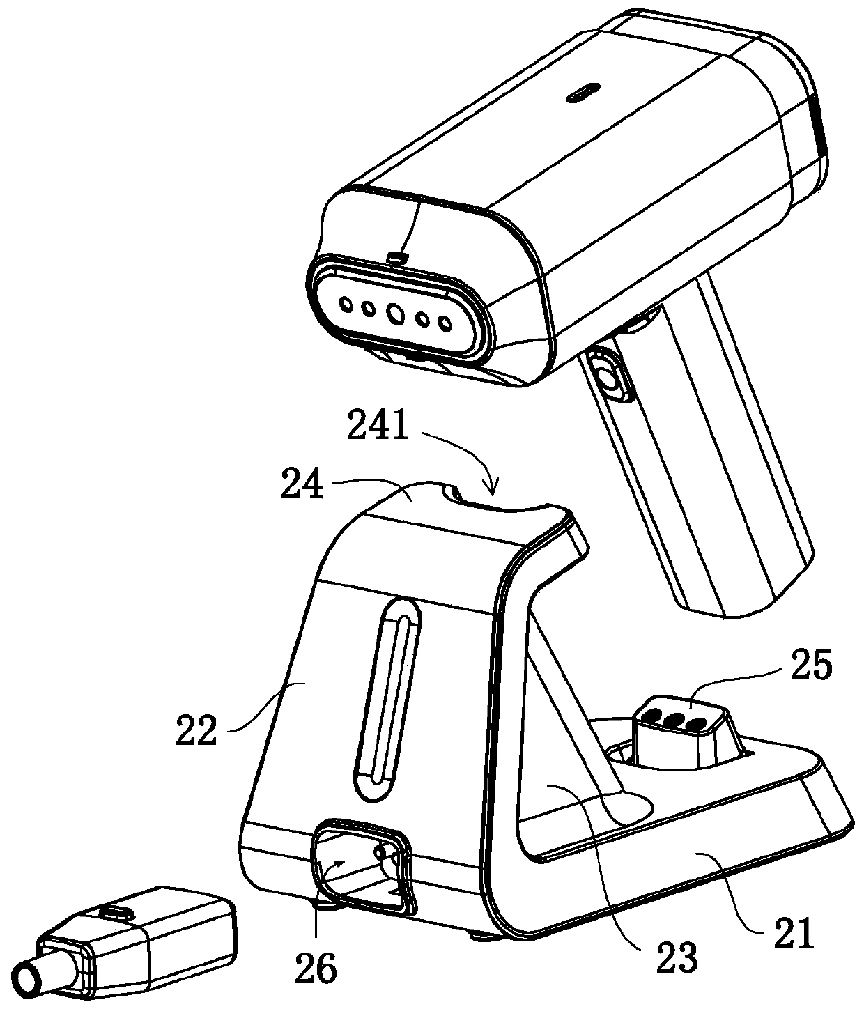
[0089] In step S100 , the steam brush 10 is connected to the power supply stand 20 . Specifically, the first power socket 121 of the steam brush 10 is connected to the power transmission head 25 , the main body 11 leans against the support platform 24 , one end of the plug element 30 is connected to the mains, and the other end is connected to the second power socket 26 .
[0090] In step S102 , the commercial power supplies power to the steam generator 13 to heat it, and at the same time charges the lithium battery 16 .
[0091] In step S106, the indicator light indicates when the steam generator 13 is heated to a preset temperature.
[0092] Step S108 , remove the steam brush 10 , press the switch element 18 to drive the water pump 19 to work, and transport the liquid medium in the water storage container 15 to the steam generator 13 to ...
PUM
 Abstract
Description
Claims
Application Information