A kind of anti-wind and wave dredging pipe for water conservancy construction

A wind and wave resistance and water conservancy technology, applied in water conservancy projects, water conservancy engineering equipment, instruments, etc., can solve the problems that dredging pipes are vulnerable to wind and wave impact and wear, and achieve the effects of avoiding wear, prolonging service life and reducing impact force

Active Publication Date: 2022-07-01
嘉兴市名人电器股份有限公司
View PDF0 Cites 0 Cited by
  • Summary
  • Abstract
  • Description
  • Claims
  • Application Information

AI Technical Summary

Problems solved by technology

[0005] The purpose of the present invention is to solve the problem that the above-mentioned dredging pipe is susceptible to the impact and wear of wind and waves, and to provide a wind and wave resistant dredging pipe for water conservancy construction that can greatly alleviate the impact of wind and waves and has a long service life.

Method used


Image

  • A kind of anti-wind and wave dredging pipe for water conservancy construction
  • A kind of anti-wind and wave dredging pipe for water conservancy construction
  • A kind of anti-wind and wave dredging pipe for water conservancy construction

Examples


Embodiment 1

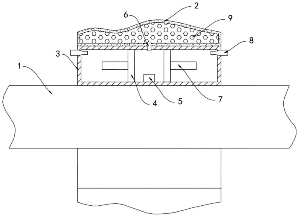
[0019] like Figure 1-2 As shown, an anti-wind and wave dredging pipe for water conservancy construction includes a pipe body 1 and an annular floating body fixedly sleeved on the outside of the pipe body 1. The annular floating body is composed of a deformation bag 2 and a fixed box 3, wherein the deformation bag 2 is sleeved on the fixed body. Outside the box 3, the deformation box 3 and the pipe body can be fixedly connected by welding, the deformation bag 2 is made of elastic rubber material, and the deformation bag 2 is filled with elastic balls 9, which can play a good supporting role. To prevent excessive deformation of the deformation capsule 2 due to the excessive impact force of the waves, the internal wear of the deformation capsule 2 is reduced, and the wind and wave resistance of the deformation capsule 2 is further improved. 4. There is a limit block 5 between the two slip rings 4, the limit block 5 is fixedly connected to the inner side wall of the fixed box 3, ...

Embodiment 2

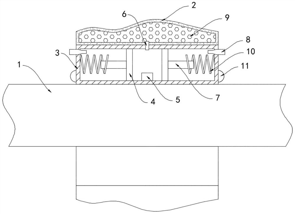
[0024] like image 3 As shown, the difference between this embodiment and Embodiment 1 is that an electromagnetic spring 10 is installed in the fixed box 3, the electromagnetic spring 10 is sleeved outside the permanent magnet column 7, and an LED light 11 is installed outside the fixed box 3, and the LED light 11 is electrically connected to both ends of the electromagnetic spring 10 to form a closed loop.

[0025] In this embodiment, the deformation capsule 2 is deformed by the impact of wind and waves, and the air pressure drives the two permanent magnet columns 7 away from each other. Because the farther the two permanent magnet columns 7 are, the smaller the magnetic attraction force is. 7 After the distance is far, the attractive force between them cannot offset the impact force of the waves. At this time, the permanent magnet column 7 is close to the electromagnetic spring 10. According to the distance from the electromagnetic induction, the electromagnetic spring 10 an...


PUM


Abstract

The invention belongs to the field of water conservancy construction, and in particular relates to a wind and wave dredging pipe for water conservancy construction, comprising a pipe body and an annular floating body fixedly sleeved on the outside of the pipe. Two slip rings are sealed and slidably connected to the inner side wall of the box, and a limit block is arranged between the two slip rings, the limit block is fixedly connected to the inner side wall of the fixed box, and a limit block is provided above the The guide pipe runs through the side walls of the fixed box and the deformation bag in turn, and permanent magnet columns are fixedly connected to the sides of the two slip rings that are far away from each other. A through hole is arranged on the side wall of the fixed box, and a whistle pipe is installed in the through hole. In the invention, the impact force of the waves on the pipe body laterally drives the two permanent magnet columns to move, and the work is converted into magnetic potential energy along the parallel direction of the pipe body, which reduces the impact of the waves on the pipe body and greatly prolongs the service life of the dredging pipe.

Description

technical field [0001] The invention belongs to the field of water conservancy construction, in particular to a wind and wave dredging pipe for water conservancy construction. Background technique [0002] The dredging pipeline is one of the indispensable components in the construction of water conservancy projects. Its main function is to clean up the steel pipelines that transport sediment, mud and other mixed debris. Land reclamation for the construction of wharfs, port areas and port-side industrial areas, coastal urban land and recreational and leisure land, shore and beach maintenance, water conservancy flood control and dredging of reservoir areas, improvement and ecological restoration of rivers, lakes and seas and other water environments, as well as various types of water resources. Construction and landfilling of pipeline trenches. [0003] In the actual operation and use of the dredging pipe, due to the large wind and waves on the sea surface, the floating body,...

Claims


Application Information

Patent Timeline
Patent Type & Authority Patents(China)
IPC IPC(8): E02F7/10E02B1/00F21V33/00G08B5/36F21Y115/10
CPCE02F7/10E02B1/00F21V33/00G08B5/36F21Y2115/10
Inventor 郭新生
Owner 嘉兴市名人电器股份有限公司
Why Eureka
Try Eureka