Concrete filled steel tubular column steel-reinforced concrete beam ring beam joint formwork reinforcing piece and method

A technology of concrete-filled steel tube columns and steel-reinforced concrete, which is applied in the fields of formwork/formwork/work frame, construction components on-site preparation, construction, etc. It can solve problems such as the influence of steel bar installation, grout leakage, and exposed screw rods, etc., to achieve Save input costs, improve efficiency, and avoid impact effects

Pending Publication Date: 2020-07-31
CHINA RAILWAY CONSTR ENG GROUP
View PDF0 Cites 2 Cited by
  • Summary
  • Abstract
  • Description
  • Claims
  • Application Information

AI Technical Summary

Problems solved by technology

[0004] However, the existing scheme has the following disadvantages: ①The screw rod needs to be welded to the steel column in advance, which has a certain impact on the installation of the steel bar in the enlarged joint area of ​​the ring beam; ②When the concrete is poured, the reinforcement screw is prone to leakage; ③The bottom formwork and the side formwork The joints are not strict, which is easy to cause slurry leakage; ④ When removing the formwork, it is difficult to remove the formwork due to the influence of the exposed screw rod; Afterwards, mortar is used for plugging and repairing

Method used


Image

  • Concrete filled steel tubular column steel-reinforced concrete beam ring beam joint formwork reinforcing piece and method
  • Concrete filled steel tubular column steel-reinforced concrete beam ring beam joint formwork reinforcing piece and method
  • Concrete filled steel tubular column steel-reinforced concrete beam ring beam joint formwork reinforcing piece and method

Examples


specific Embodiment 1

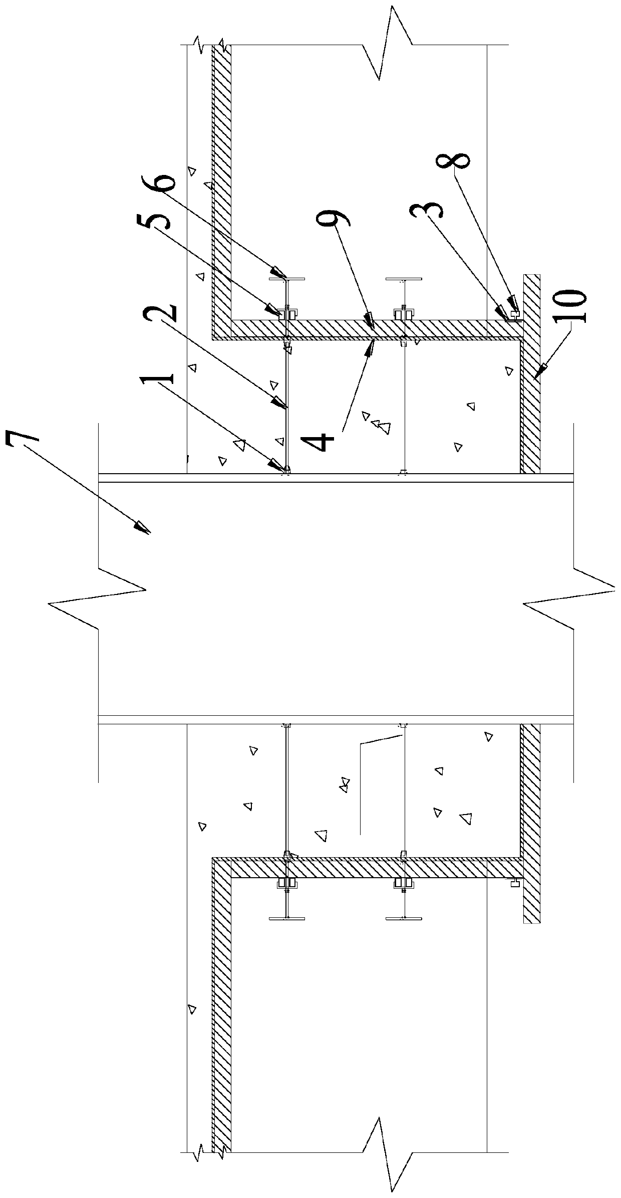
[0063] Specific embodiment one, such as Figure 1-8 As shown, a formwork reinforcement for steel reinforced concrete beam ring beam joints of concrete filled steel pipe columns includes a first tapered sleeve 1, a round steel tie rod 2, a steel flat belt 3, an arc formwork 4, and arc-shaped double pipes 5, T-shaped connecting rod 6;

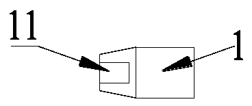
[0064] The first tapered sleeve 1 is welded to the steel column 7, and the first tapered sleeve is provided with several rows, and each row is evenly welded to the outer wall of the steel column; as figure 2 As shown, the first tapered sleeve 1 is an integral structure including a circular frustum sleeve and a cylindrical end, and the side of the cylindrical end close to the steel column is provided with a bevel, which is convenient for welding with the steel column 7; the first An internal thread 11 is provided inside the frustum sleeve of the tapered sleeve 1 .

[0065] The round steel tie rod 2, such as image 3 As shown, both ends are pro...


PUM


Abstract

The invention discloses a concrete filled steel tubular column steel-reinforced concrete beam ring beam joint formwork reinforcing piece which comprises a first conical sleeve, a round steel pull rod,a steel flat belt, an arc formwork, arc-shaped double square tubes and a T-shaped connecting rod. The first conical sleeve is connected with a steel column in a welded mode, screw threads are arranged at the two ends of the round steel pull rod, one end of the round steel pull rod is in threaded connection with the first conical sleeve, and the other end of the round steel pull rod is in threadedconnection with a second conical sleeve of the T-shaped connecting rod; the arc formwork is an arc-shaped clear water formwork; the arc-shaped double square tubes are two square tubes with radian; the T-shaped connecting rod comprises a T-shaped round steel main rod, the second conical sleeve is welded to the end, a main stress rod is sleeved with a first nut and perforated channel steel, and a perforated hole is formed in the middle of the perforated channel steel. The round steel pull rod is installed after ring beam span joint steel bars are installed, the influence on steel bar installation can be avoided, and the steel bar installation efficiency is improved; and the arc-shaped steel flat belt with the self-locking function, the problem that a splicing seam of a side mold and a bottom mold is not tight is solved.

Description

technical field [0001] The invention relates to the technical field of building node reinforcement, and more specifically relates to a steel reinforced concrete beam ring beam node formwork reinforcement member and method for a concrete filled steel tube column. Background technique [0002] The ring beam joints between the CFST column and the steel reinforced concrete beam are in the shape of a cylinder, and the height of the enlarged joint of the ring beam is slightly higher than the height of the beam, and is divided into four arc-shaped single-sided columns by the beam connected to the ring beam joint. The supporting form of the side formwork of the beam joint is a difficult point. [0003] In the existing scheme, the bottom formwork of the enlarged joint of the ring beam is cut from a wooden formwork into a circular formwork of the size of the ring beam joint, and the side formwork adopts an arc-shaped wooden formwork. The bottom formwork is supported by steel pipe sca...

Claims


Application Information

Patent Timeline
Patent Type & Authority Applications(China)
IPC IPC(8): E04B1/58E04B1/30E04G13/00
CPCE04B1/185E04B1/30E04G13/00
Inventor 陈惠强王福全刘智杨春林陈虹文张宁曾波孙宇甘文民段渭峰
Owner CHINA RAILWAY CONSTR ENG GROUP
Why Eureka
Try Eureka