Building mounting anchor plate

An installation and anchor plate technology, used in buildings, building components, building structures, etc., can solve the problems of cracks at joints, inconvenient adjustment, concentrated force, etc. Effect

Inactive Publication Date: 2020-07-31
广东东兴建设工程有限公司
View PDF7 Cites 0 Cited by
  • Summary
  • Abstract
  • Description
  • Claims
  • Application Information

AI Technical Summary

Problems solved by technology

[0004] Most of the anchor plates used for installation in existing buildings are directly welded to the screws, gaskets, nuts, etc. that connect the rear anchor plate to the concrete. The welding position of the external screws is fixed, which is inconvenient to adjust during the subsequent curtain wall installation, resulting in difficulty in installation ; At the same time, the part of the anchor plate embedded in the concrete is concentrated, which is easy to cause cracks and loosening at the connection, and the stability is poor

Method used


Image

  • Building mounting anchor plate
  • Building mounting anchor plate
  • Building mounting anchor plate

Examples


Embodiment Construction

[0018] The following will clearly and completely describe the technical solutions in the embodiments of the present invention with reference to the accompanying drawings in the embodiments of the present invention. Obviously, the described embodiments are only some, not all, embodiments of the present invention. Based on the embodiments of the present invention, all other embodiments obtained by persons of ordinary skill in the art without making creative efforts belong to the protection scope of the present invention.

[0019] In the description of the present invention, it should be noted that the orientation or positional relationship indicated by the terms "vertical", "upper", "lower", "horizontal" etc. is based on the orientation or positional relationship shown in the drawings, and is only In order to facilitate the description of the present invention and simplify the description, it does not indicate or imply that the device or element referred to must have a specific o...


PUM


Abstract

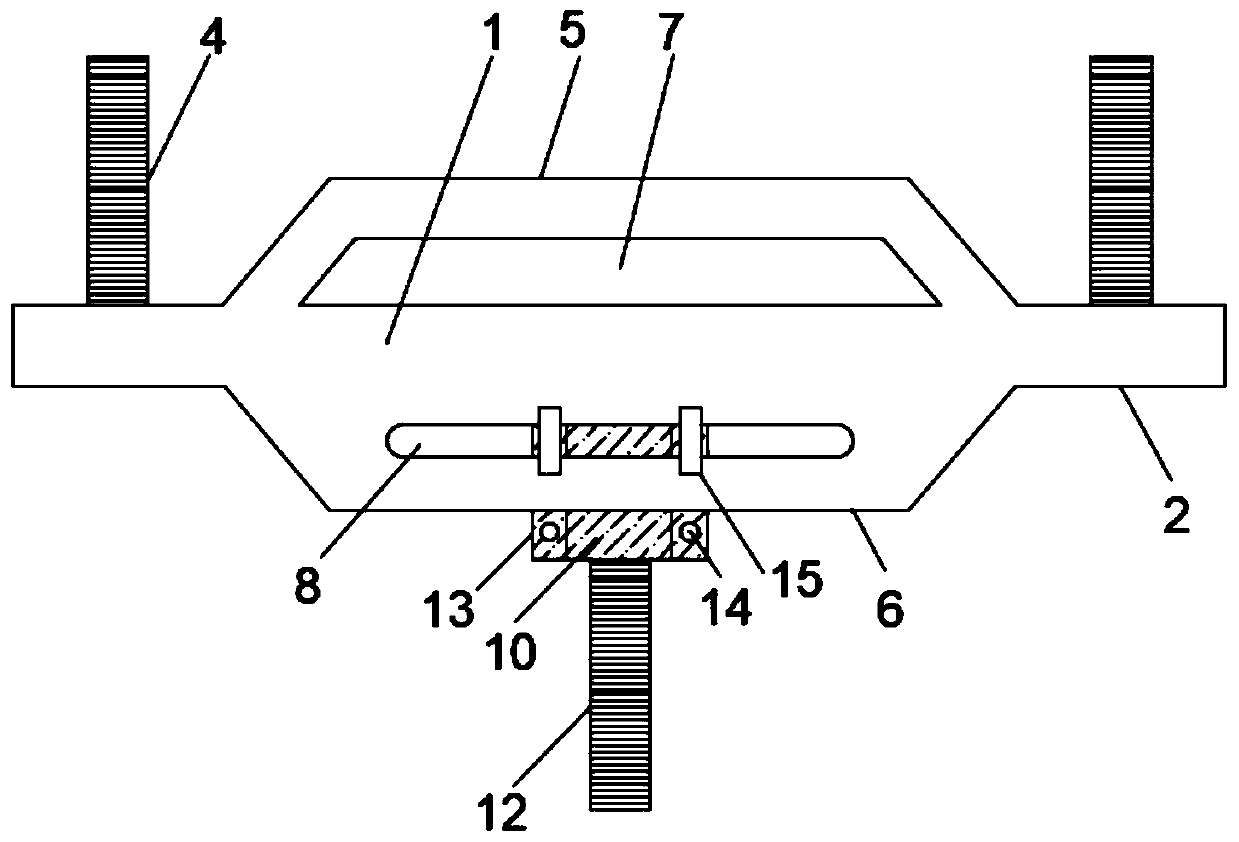
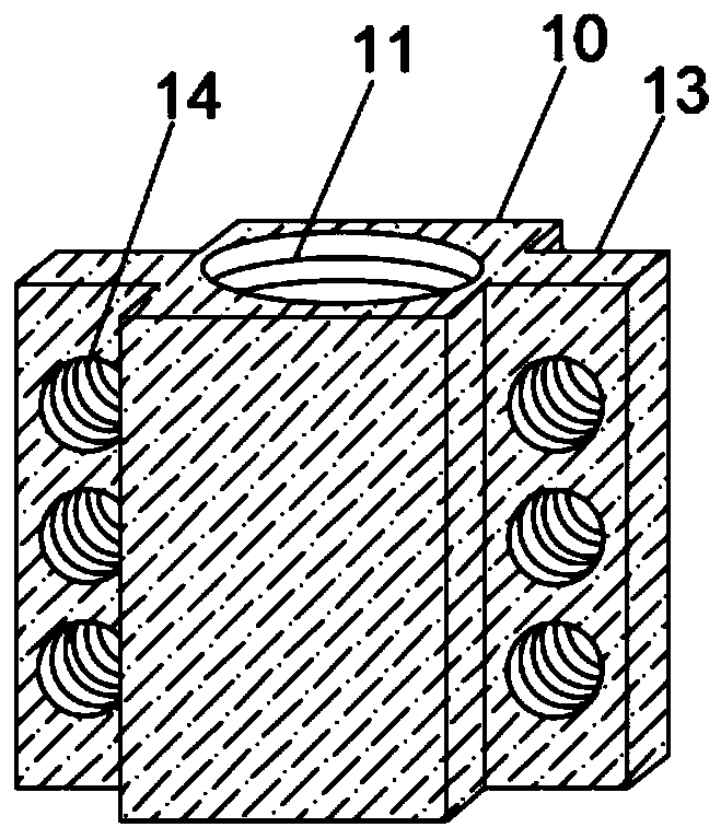
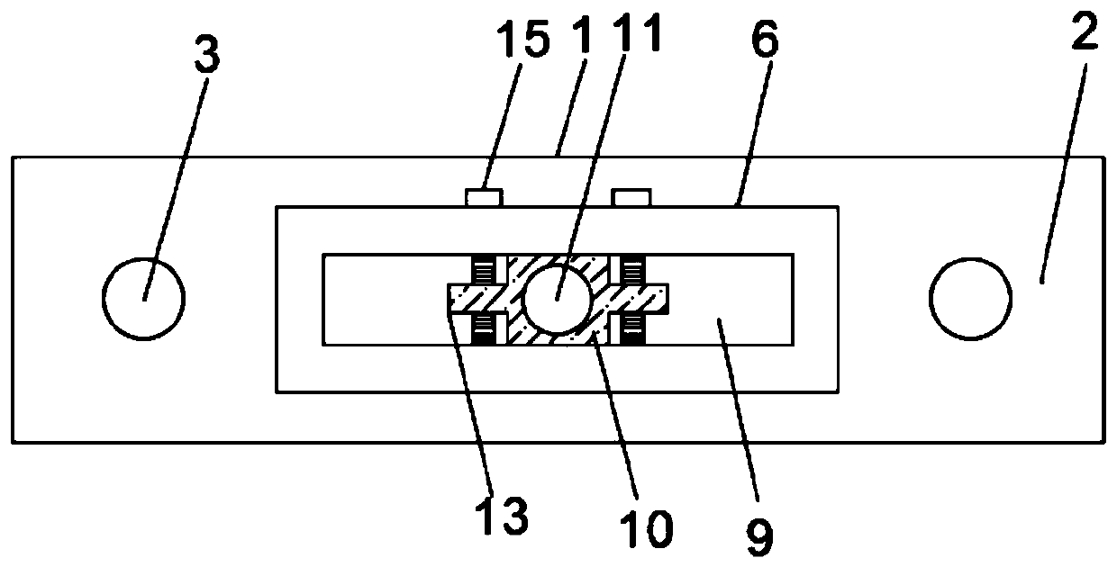
The invention belongs to the field of building mounting and specifically discloses a building mounting anchor plate. The building mounting anchor plate comprises an anchor plate main body; the two sides of the middle part of the anchor plate main body are arched outwards to correspondingly form a pre-embedded part and a force bearing part; the middle part of the pre-embedded part is hollowed out to form a concrete filling groove; a locating groove is formed in the upper surface of the force bearing part; an adjusting groove is formed in the end surface of the force bearing part; a linking block is embedded into the adjusting groove; and the middle parts of the two sides of the linking block protrude outwards to form reinforcing plates. The middle part of the pre-embedded part is hollowed out to form the concrete filling groove to fill the concrete slurry so that the pre-embedded part is sufficiently embedded into a wall body; and therefore, the stress on the connecting plate is dispersed so that wall body cracks are uneasily caused and loosening at the connecting part is also uneasily caused; as the adjusting groove is formed in the force bearing part and the linking block is embedded into the adjusting groove to connect the force bearing part with an external screw rod, welding and fixing are not needed and the later detaching is made convenient; as the external screw rod canslide within the adjusting groove with the linking block, and the extending length of the linking block in the adjusting groove can be adjusted, the position of the external screw rod is convenientlyadjusted according to needs, and the mounting of a curtain wall is made convenient.

Description

technical field [0001] The invention relates to the field of building installation, in particular to an anchor plate for building installation. Background technique [0002] Construction installation refers to the general term for construction, repair, installation and other engineering operations, including heating and cooling, sanitation, ventilation, lighting and various pipeline facilities connected to buildings; it also includes foundations, pillars, operating platforms, various Furnace and metal structure engineering. [0003] China has now become the country that builds the most curtain walls in the world. The building curtain wall is the outer protective structure that uses the main building as the carrier. The main load of the building curtain wall is the anchor structure connected with the concrete. It not only bears the weight of the curtain wall, but also bears a series of external forces such as wind resistance and earthquakes. Bearing capacity requirements, i...

Claims


Application Information

Patent Timeline
Patent Type & Authority Applications(China)
IPC IPC(8): E04B2/88E04B1/41E04G21/14
CPCE04B1/41E04B2/88E04G21/14
Inventor 龚梅满
Owner 广东东兴建设工程有限公司
Why Eureka
Try Eureka