
Metal base substrate

A technology of metal base and metal substrate, which is applied in the direction of metal pattern materials, circuit substrate materials, metal layered products, etc., can solve the problems of high solder stress, high thermal expansion rate, and difficulty in fully reducing stress, so as to prevent solder cracks , The effect of suppressing the occurrence of solder cracks

Pending Publication Date: 2021-02-26
MITSUBISHI MATERIALS CORP
View PDF3 Cites 0 Cited by
  • Summary
  • Abstract
  • Description
  • Claims
  • Application Information

AI Technical Summary

Problems solved by technology

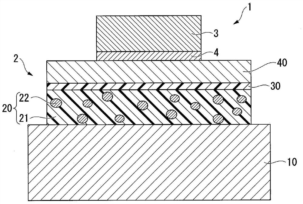
[0007] However, the metal-clad laminate as described in Patent Document 1 generally has a large coefficient of thermal expansion, and an electronic component generally made of ceramics has a low coefficient of thermal expansion.
When the difference in thermal expansion coefficient between the metal-clad laminate and the electronic component increases, the stress applied to the solder that joins the electronic component and the metal base substrate by turning on / off the electronic component or cooling and heating cycles due to the external environment increases. , there is a problem that solder cracks are prone to occur
[0008] On the other hand, the silicone resin described in Patent Document 2 has low elasticity compared with polyimide resin or polyamideimide resin.
However, since the thermally conductive filler is contained in the insulating layer of the metal base substrate, the elasticity of the insulating layer is lowered compared to the silicone resin alone
Therefore, it is difficult to sufficiently reduce the stress applied to the solder that joins the electronic component and the metal base substrate by cooling and heating cycles only by using a silicone resin as the resin for the insulating layer.

Method used


Image

  • Metal base substrate
  • Metal base substrate
  • Metal base substrate

Examples


Embodiment

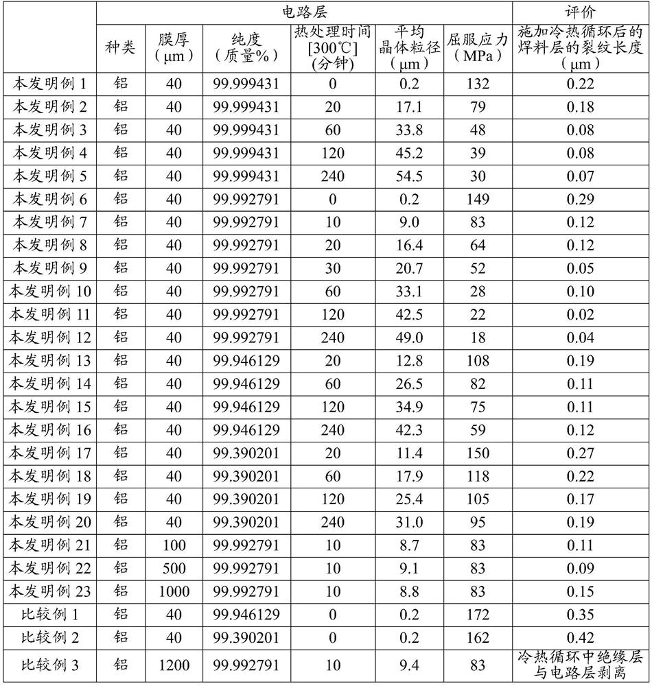
[0054] Hereinafter, the effects of the present invention will be described through examples.

[0055] [Example 1 of the present invention]

[0056] 4,4'-Diaminodiphenyl ether and NMP (N-methyl-2-pyrrolidine) were placed in a 300 mL separable flask. The amount of NMP was adjusted so that the density|concentration of the obtained polyamic acid might become 40 mass %. After stirring at room temperature to completely dissolve 4,4'-diaminodiphenyl ether, a predetermined amount of tetracarboxylic dianhydride was added little by little so that the internal temperature did not exceed 30°C. Then, stirring was continued for 16 hours under a nitrogen atmosphere to prepare a polyamic acid (polyimide precursor) solution.

[0057] Alumina particles (average particle diameter: 0.5 μm) were prepared as ceramic particles (thermally conductive filler). The prepared 1.0 g of alumina particles and 10 g of NMP were mixed and subjected to ultrasonic treatment for 30 minutes to prepare an alumina...

example 4

[0076] A metal base substrate was fabricated in the same manner as in Example 1 of the present invention, except that copper foil whose film thickness, purity, average grain size, and yield stress (0.2% yield strength) were the values ​​shown in Table 2 below was used instead of aluminum foil. , and measure the crack length of the solder layer after applying the thermal cycle. The average crystal grain diameter and yield stress (0.2% yield stress) of copper foil were adjusted by heat-processing at the temperature of 300 degreeC for the heat-treatment time shown in following Table 2. In addition, regarding the purity of the copper foil, except that the impurity elements are Na, Mg, Si, Al, P, K, Ca, Ti, V, Cr, Mn, Fe, Co, Ni, Zn, Ga, Ge, Nb, Mo, Ru, Pd, Ag, In, Sn, Sb, Ba, Hf, W, Pt, Au, Pb, and Bi were measured in the same manner as the purity of aluminum foil. About the average crystal grain diameter of copper foil, it measured similarly to the average crystal grain diameter...


PUM

PropertyMeasurementUnit
thicknessaaaaaaaaaa
yield stressaaaaaaaaaa

Abstract

A metal base substrate (2) obtained by layering, in this order, a metal substrate (10), an insulating layer (20), and a circuit layer (40), wherein the insulating layer (20) contains a resin, the circuit layer (40) exhibits a film thickness in the range of 10-1,000 [mu]m, inclusive, and the yield stress thereof is in the range of 10-150 MPa, inclusive.

Description

technical field [0001] The present invention relates to a metal base substrate. [0002] This application claims priority based on Patent Application No. 2018-134788 filed in Japan on July 18, 2018, and the content thereof is hereby cited. Background technique [0003] A metal base substrate is known as one of substrates on which electronic components such as semiconductor elements are mounted. The metal base substrate is a laminate formed by sequentially laminating a metal substrate, an insulating layer, and a circuit layer. Electronic components are mounted on the circuit layer with solder. In the metal base substrate having such a structure, heat generated in the electronic component is transferred to the metal substrate via the insulating layer, and is dissipated from the metal substrate to the outside. [0004] The insulating layer of the metal base substrate is generally formed of an insulating resin composition containing a resin excellent in insulating properties ...

Claims


Application Information

Patent Timeline
Patent Type & Authority Applications(China)
IPC IPC(8): H05K1/05B32B15/08H01B5/14H01L23/12H01L23/14
CPCH01B5/14H01L23/142H01L23/3735H01L23/3737H05K1/056H05K3/0061H05K2201/0209H05K2201/0154H05K1/0204H05K1/0271H05K1/0373H05K3/3431H01L23/145H05K1/09B32B15/08H01L23/12H01L23/14H01B17/62H01L23/53214H01L27/013H05K3/34
Inventor 石川史朗野中荘平
Owner MITSUBISHI MATERIALS CORP
Learn More