Oil sprayer valve structure

A fuel injector and injector body technology, which is applied to machines/engines, fuel injection devices, engine components, etc., can solve the problems of short service life, many sealing contact surfaces, and easily damaged fuel injectors, so as to improve service life. , The effect of reducing the damage of cavitation and increasing the service life

Inactive Publication Date: 2020-07-31
CHANGSHU INSTITUTE OF TECHNOLOGY
View PDF7 Cites 0 Cited by
  • Summary
  • Abstract
  • Description
  • Claims
  • Application Information

AI Technical Summary

Problems solved by technology

[0002] The control valve is an important part of the fuel injector. It can accurately control the opening of the fuel injector and is the key factor affecting the precise control of the fuel injector. Now the injection pressure requirements of the fuel injector are constantly increasing, and the injection pressure is required to be above 200MPa. At the same time, the hydraulic pressure in the cavity of this type of control valve is also continuously increasing. The oil in the control cavity drops from a high pressure (200MPa and above) to 0MPa, which will cause cavitation damage. The higher the oil pressure, the more serious the cavitation damage. The easier the oiler is damaged, the shorter the service life
[0003] In the prior art, for example, the patent structure of the publication number: CN103967666B does not have a structure for controlling the pressure drop of the cavity slowly, and high pressure will cause cavitation damage, thereby limiting the working pressure of this type of injector; publication number: DE10190272B4 patent technical manual attached Image 6 The restri

Method used


Image

  • Oil sprayer valve structure
  • Oil sprayer valve structure
  • Oil sprayer valve structure

Examples


Embodiment Construction

[0022] The present invention will be further described below in conjunction with embodiment, should be understood that these embodiments are only used to illustrate the present invention and are not intended to limit the scope of the present invention, after having read the present invention, those skilled in the art can modify various equivalent forms of the present invention All fall within the scope defined by the appended claims of this application.

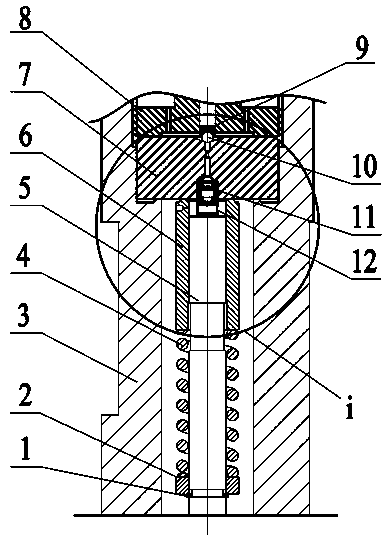
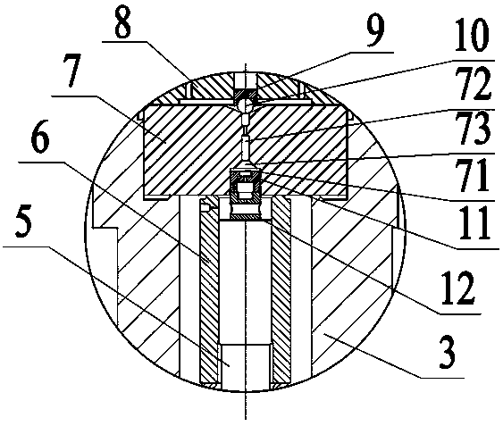
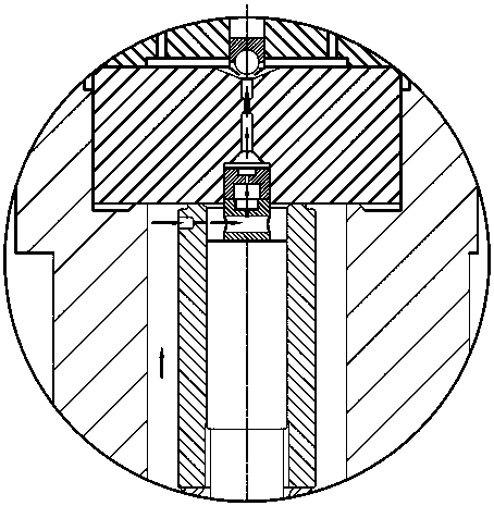
[0023] Please combine Figure 1 to Figure 3 As shown, the fuel injector valve structure involved in this embodiment, such as figure 1 As shown, it includes a control plunger 5, a valve sleeve 6, an orifice 7 and a fastening valve seat 8. The fastening valve seat 8 and the injector body 3 are fixed by threaded connection, and the orifice plate 7 is fixed to the injector body 3. Inside, the valve sleeve 6 is sleeved on the outer circumference of the control plunger 5 to cooperate with the control plunger 5 , and the gap betwe...


PUM

PropertyMeasurementUnit
Diameteraaaaaaaaaa

Abstract

The invention discloses an oil sprayer valve structure. The oil sprayer valve structure comprises a control plunger, a valve sleeve, a pore plate and a fastening valve seat, wherein the pore plate, the valve sleeve and the control plunger define a control cavity. The oil sprayer valve structure further comprises a first pressure buffering floating column and a second pressure buffering floating column which are vertically stacked on the top surface of the control plunger, and the first pressure buffering floating column and the second pressure buffering floating column are both cylindrical; the pore plate is provided with a pore plate oil outlet and a constraint hole matched with the first pressure buffering floating column and the second pressure buffering floating column; the constrainthole and the pore plate oil outlet communicate through a conical hole section and penetrate through the pore plate; the first pressure buffering floating column is completely arranged in the constraint hole; one part of the second pressure buffering floating column is arranged in the constraint hole; the first pressure buffering floating column and the second pressure buffering floating column canmove up and down in the constraint hole; the first pressure buffering floating column is provided with a first oil channel; the second pressure buffering floating column is provided with a second oilchannel; and the first oil channel is communicated with the control cavity through the second oil channel. The oil sprayer valve structure reduces pressure of oil twice, can solve the problem of cavitation damage of a high-pressure sprayer, prolongs the service life of the sprayer and accelerates action response.

Description

technical field [0001] The invention relates to a control valve structure, in particular to a fuel injector valve structure, and belongs to the technical field of high-pressure common rail fuel injection. Background technique [0002] The control valve is an important part of the fuel injector. It can precisely control the opening of the fuel injector and is the key factor affecting the precise control of the fuel injector. Now the injection pressure requirements of the fuel injector are constantly increasing, and the injection pressure is required to be above 200MPa. At the same time, the hydraulic pressure in the cavity of this type of control valve is also continuously increasing. The oil in the control cavity drops from high pressure (200MPa and above) to 0MPa, which will cause cavitation damage. The higher the oil pressure, the more serious the cavitation damage. The easier the oiler is damaged, the shorter the service life. [0003] In the prior art, for example, the ...

Claims


Application Information

Patent Timeline
IPC IPC(8): F02M51/06F02M61/06F02M61/16F02M61/18
CPCF02M51/061F02M61/06F02M61/161F02M61/18
Inventor 许广举李铭迪赵洋胡焰彬林玲刘帅
Owner CHANGSHU INSTITUTE OF TECHNOLOGY
Why Eureka
Try Eureka