Single-column control valve of ejector

A technology of injectors and control valves, which is applied in fuel injection devices, machines/engines, engine components, etc., can solve the problems of high difficulty in manufacturing and processing, many sealing contact surfaces, and short service life, so as to reduce the opening delay time and reduce the Destruction of cavitation and effect of improving service life

Inactive Publication Date: 2020-07-31
CHANGSHU INSTITUTE OF TECHNOLOGY
View PDF7 Cites 0 Cited by
  • Summary
  • Abstract
  • Description
  • Claims
  • Application Information

AI Technical Summary

Problems solved by technology

[0002] The control valve is an important part of the fuel injector. It can accurately control the opening of the fuel injector and is the key factor affecting the precise control of the fuel injector. Now the injection pressure requirements of the fuel injector are constantly increasing, and the injection pressure is required to be above 200MPa. At the same time, the hydraulic pressure in the cavity of this type of control valve is also continuously increasing. The oil in the control cavity drops from a high pressure (200MPa and above) to 0MPa, which will cause cavitation damage. The higher the oil pressure, the more serious the cavitation damage. The easier the oiler is damaged, the shorter the service life
[0003] In the prior art, for example, the patent structure of the publication number: CN103967666B does not have a structure for controlling the pressure drop of the chamber, and high pressure will cause cavitation damage, thereby limiting the working pressure of this type of injector; publication number: DE10190272B4 patent technical manual attached Image 6 The restrictor (148) and socket valve (302) shown in the figure can reduce cavitation damage, but there are many sealing contact surfaces between parts, which increases a certain leakage risk; publication number: CN101595297B patent end The ball seat valve (110) also has an inlet (122) with a pre-throttling device (126) and a diffuser (128) arranged between the pre-throttle device (126) and the valve seat (120). ), the diffuser (128) can play a pressure buffer role for high oil pressure, the pressure in the diffuser (128) decreases, and the pressure difference after the outflow in the diffuser (128) decreases, reducing cavitation damage, The one-piece structure in this patent is as attached to its description figure 2 As shown, it is a thin hole at both ends and a thick hole in the middle, so the difficulty of manufacturing and processing is very high, and the diffuser (128) of the split structure in this patent is as attached to its description. image 3 As shown, the difficulty of processing is reduced, but a sealing contact plane is added, which also increases the risk of leakage

Method used


Image

  • Single-column control valve of ejector
  • Single-column control valve of ejector
  • Single-column control valve of ejector

Examples


Embodiment 1

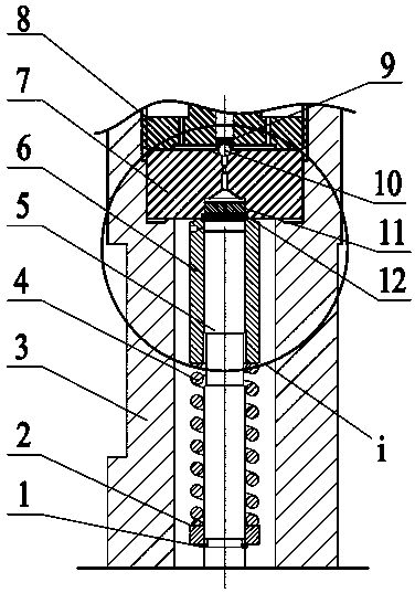
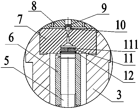
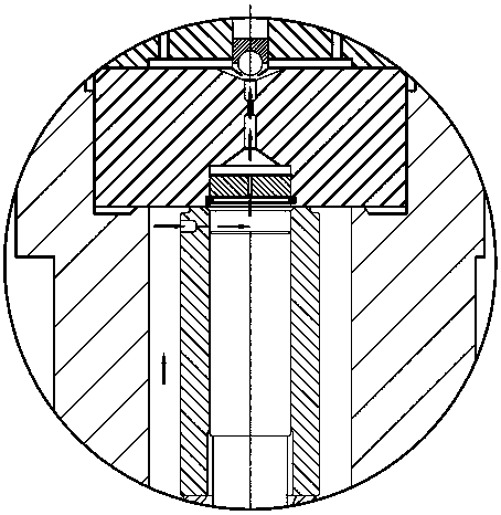
[0024] Example 1, please combine Figure 1 to Figure 3 As shown, the single-column control valve of the injector involved in this embodiment, such as figure 1 As shown, it includes a control plunger 5, a valve sleeve 6, an orifice 7 and a fastening valve seat 8. The fastening valve seat 8 and the injector body 3 are fixed by threaded connection, and the orifice plate 7 is fixed to the injector body 3. Inside, the valve sleeve 6 is sleeved on the outer circumference of the control plunger 5 to cooperate with the control plunger 5 , and the gap between the valve sleeve 6 and the control plunger 5 is between 0.005 mm and 0.012 mm. The control plunger 5, the valve sleeve 6 and the orifice 7 form a control chamber. The single-column control valve of the injector also includes a pressure-relief floating column 11, which is cylindrical, and a pressure-relief oil outlet hole 111 penetrating in the axial direction is opened in the center of the pressure-relief float 11. The diameter...


PUM


Abstract

The invention discloses a single-column control valve of an ejector. The single-column control valve comprises a control plunger, a valve sleeve, a pore plate and a fastening valve seat, wherein the pore plate, the valve sleeve and the control plunger define a control cavity. The single-column control valve further comprises a pressure-relieving floating column, wherein the pressure-relieving floating column is cylindrical, and is provided with an axially-penetrating pressure-relieving oil outlet hole; the pore plate is provided with a restraining hole and a pore plate oil outlet hole; the restraining hole is formed in the lower part of the pore plate, and is matched with the pressure-relieving floating column; the pore plate oil outlet hole communicates with the restraining hole through aconical hole section, and penetrates through the pore plate; the pressure-relieving floating column is arranged in the restraining hole; an elastic retainer ring is arranged on an opening in the lower end of the restraining hole; and the elastic retainer ring limits up-down movement of the pressure-relieving floating column in the restraining hole. The single-column control valve can solve the problem of cavitation erosion damage of a high-pressure ejector, prolongs the service life of the ejector, and accelerates action response.

Description

technical field [0001] The invention relates to a control valve, in particular to a single-column control valve of an injector, and belongs to the technical field of high-pressure common rail fuel injection. Background technique [0002] The control valve is an important part of the fuel injector. It can precisely control the opening of the fuel injector and is the key factor affecting the precise control of the fuel injector. Now the injection pressure requirements of the fuel injector are constantly increasing, and the injection pressure is required to be above 200MPa. At the same time, the hydraulic pressure in the cavity of this type of control valve is also continuously increasing. The oil in the control cavity drops from high pressure (200MPa and above) to 0MPa, which will cause cavitation damage. The higher the oil pressure, the more serious the cavitation damage. The easier the oiler is damaged, the shorter the service life. [0003] In the prior art, for example, t...

Claims


Application Information

Patent Timeline
IPC IPC(8): F02M51/06F02M61/06F02M61/16F02M61/18
CPCF02M51/061F02M61/06F02M61/161F02M61/18
Inventor 许广举赵洋李铭迪林玲胡焰彬刘帅
Owner CHANGSHU INSTITUTE OF TECHNOLOGY
Why Eureka
Try Eureka