A Radial Partitioned Oil Slinger

A technology of oil flinger and disc body, which is applied in the field of power unit combustion, which can solve the problems of small fuel flow change range and lower combustion efficiency, and achieve the effects of improving distribution uniformity, combustion efficiency and radial uniformity

Active Publication Date: 2021-10-12
INST OF ENGINEERING THERMOPHYSICS - CHINESE ACAD OF SCI
View PDF0 Cites 0 Cited by
  • Summary
  • Abstract
  • Description
  • Claims
  • Application Information

AI Technical Summary

Problems solved by technology

Continuing to increase the oil-gas ratio will lead to a rich oil working situation near the oil thrower, and the combustion efficiency will be significantly reduced
Researchers at home and abroad have proposed some measures to increase the atomization characteristics of the oil flinger, such as changing the shape of the nozzle outlet, increasing the swirl structure and cavity structure, and increasing the atomization cone angle. It is more applicable in the combustion chamber, and the range of fuel flow for efficient work is small. These oil flinger nozzles cannot solve the above-mentioned problems existing in larger-sized combustion chambers.

Method used


Image

  • A Radial Partitioned Oil Slinger
  • A Radial Partitioned Oil Slinger
  • A Radial Partitioned Oil Slinger

Examples


Embodiment Construction

[0025] In order to make the technical means, creative features, goals and effects of the present invention easy to understand, the present invention will be further described in detail below in conjunction with specific embodiments and with reference to the accompanying drawings.

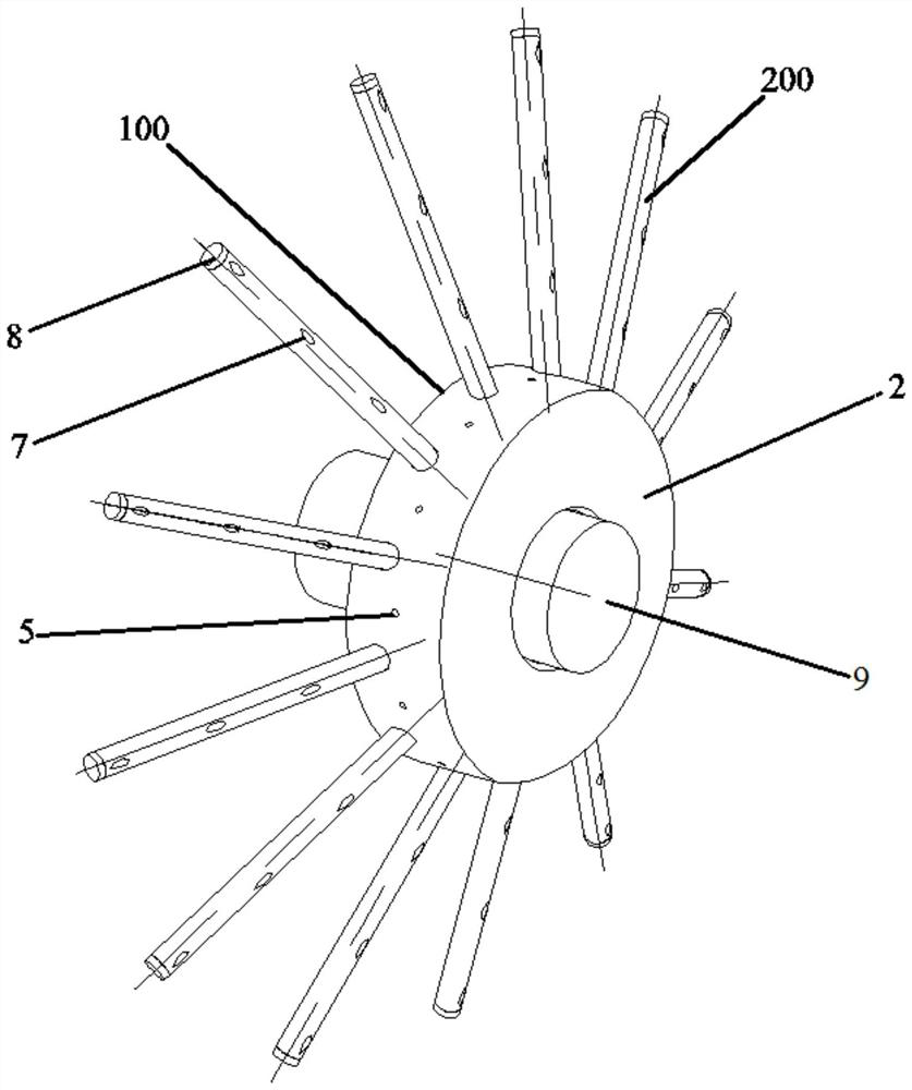
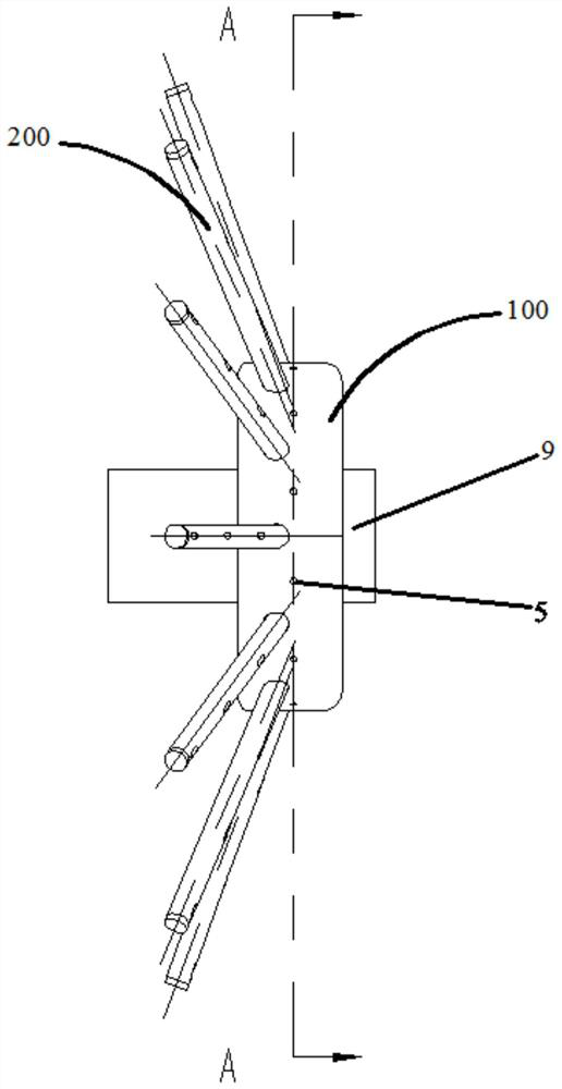
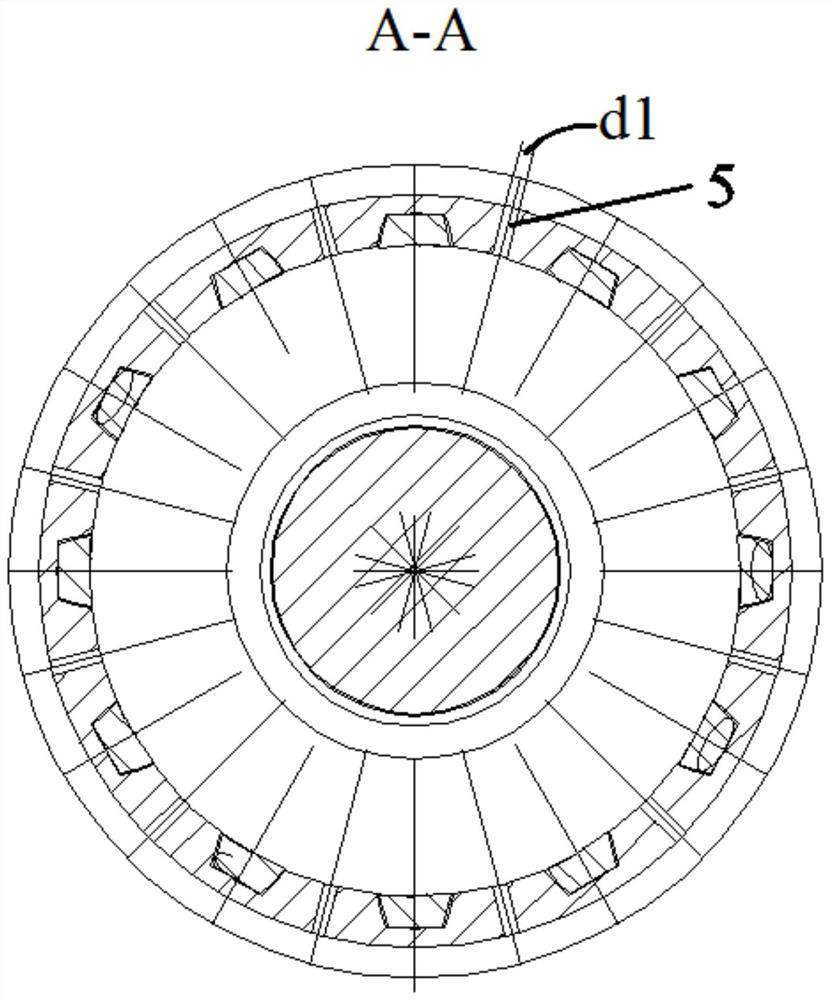
[0026] like Figure 1-6 As shown, the radially partitioned oil flinger provided by the present invention is used to inject fuel in the combustion chamber of the turbine engine, including: the oil flinger disc body 100, which is connected with the rotating shaft 9 of the turbine engine; a plurality of oil supply pipes 200, It is arranged on the oil thrower body 100; and a plurality of nozzles 5 are arranged at different radial positions of the oil thrower body 100 and the plurality of oil supply pipes 200 for spraying fuel into the combustion chamber.

[0027] Based on the above embodiments, as an optional embodiment, the front wall 1 , the rear wall 2 and the annular wall surface 3 of the oil throw...


PUM


Abstract

The present invention provides a radially partitioned oil thrower, which is used for fuel injection in the combustion chamber of a turbine engine, comprising: an oil thrower body connected to the rotating shaft of the turbine engine; a plurality of oil supply pipes arranged on the on the oil pan body; and a plurality of nozzles, arranged at different radial positions of the oil flinger body and the plurality of oil supply pipes, for spraying fuel into the combustion chamber. The oil thrower with radial partitions provided by the present invention realizes efficient matching of fuel and air by adding oil supply pipes and nozzles with nozzles on the body of the oil thrower, thereby improving the efficiency of the combustion chamber under the condition of large oil-gas ratio. The high combustion efficiency can be applied in high-performance combustion chambers with larger size and wider working boundary requirements.

Description

technical field [0001] The invention belongs to the technical field of power plant combustion, and in particular relates to a radially partitioned oil flinger. Background technique [0002] In liquid-fueled combustors, the fuel is injected into the air in a continuous flow of liquid through nozzles, where it is atomized into distinct droplets. The droplets absorb heat from the surrounding environment and evaporate, mix with oxygen in the air and burn. Under the same mass flow rate, the smaller the size of the droplet, the larger the surface area of ​​the droplet, and the faster the rate of evaporation and combustion. The atomization quality and evaporation rate of fuel oil are important factors to increase the fuel combustion rate, improve combustion efficiency, shorten the length of the combustion chamber, and reduce the structural weight. [0003] Oil slinger nozzle is a typical structure in the main combustion chamber of small and medium aero-engines. The oil slinger is...

Claims


Application Information

Patent Timeline
Patent Type & Authority Patents(China)
IPC IPC(8): F23R3/38
CPCF23R3/38
Inventor 邓爱明赵庆军房爱兵胡斌赵巍
Owner INST OF ENGINEERING THERMOPHYSICS - CHINESE ACAD OF SCI
Why Eureka
Try Eureka