Positioning device for blood drawing

A positioning device and positioning rod technology, applied in the field of medical equipment, can solve the problems of blood flow obstruction, movement, and adverse effects of blood pumping in patients

Active Publication Date: 2020-08-04
THE FIRST AFFILIATED HOSPITAL OF ARMY MEDICAL UNIV
View PDF12 Cites 3 Cited by
  • Summary
  • Abstract
  • Description
  • Claims
  • Application Information

AI Technical Summary

Problems solved by technology

[0004] When the above-mentioned machine is in use, the first sub-component and the second sub-component are squeezed on the patient's arm from both sides to realize the clamping and fixing of the patient's arm, but the first sub-component and the second sub-component exert a large force on the patient. When under pressure, on the one hand, it is easy to move the skin and muscles of the patient's arm, causing the position of the blood vessel to shift, which will adversely affect the puncture of the needle; on the other hand, it will squeeze the patient's arm, hindering the flow of the patient's blood , adversely affect the pumping of blood
And if the first component and the second component exert less pressure on the patient, it will easily lead to the inability to fully fix the patient's arm. After the needle penetrates the human body, the patient will easily conditioned reflex under the effect of the sudden pain. Keeping your hands back can easily cause the needle to break

Method used


Image

  • Positioning device for blood drawing
  • Positioning device for blood drawing
  • Positioning device for blood drawing

Examples


Embodiment 1

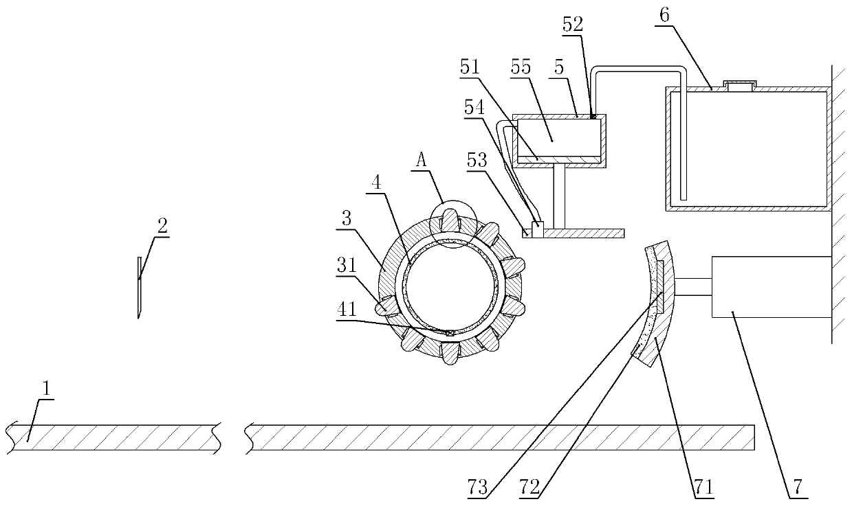
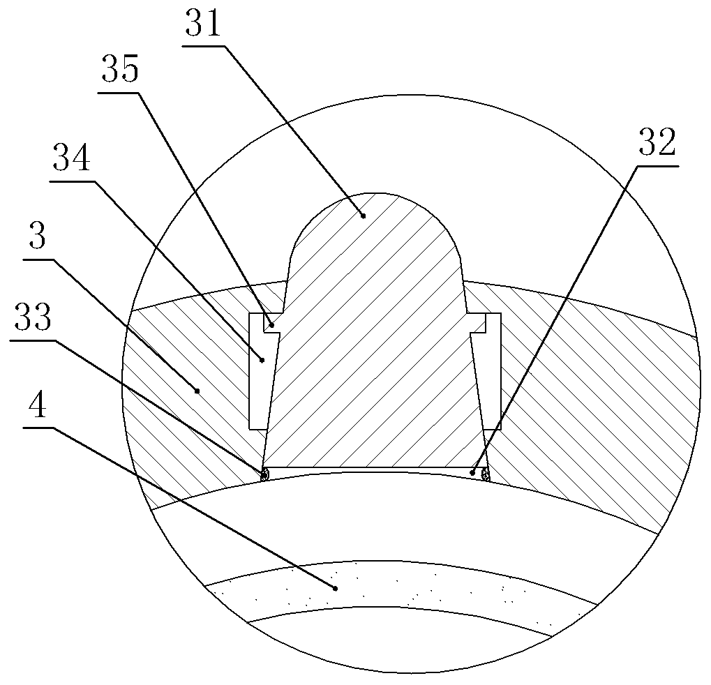
[0034] Positioning devices for blood draws, such as figure 1 and figure 2 As shown, it includes a frame, a positioning rod, a positioning plate 1 and a limit unit. In this embodiment, the needle 2 of the blood pumping device is vertically arranged with the needle point facing down as an example. The positioning plate 1 is located below the needle 2 and is welded on the machine. On the rack, the positioning rod is located between the positioning plate 1 and the needle 2 and on the right side of the needle 2. The positioning rod is arranged horizontally and is threadedly connected with the frame, and the limiting unit is located on the right side of the positioning rod.

[0035]The limiting unit in this embodiment includes a limiting plate 71 and a driver. The limiting plate 71 is located on the right side of the positioning rod and is opposite to the positioning rod. The limiting plate 71 is arc-shaped and the right end of the limiting plate 71 is welded on the hydraulic cyli...

Embodiment 2

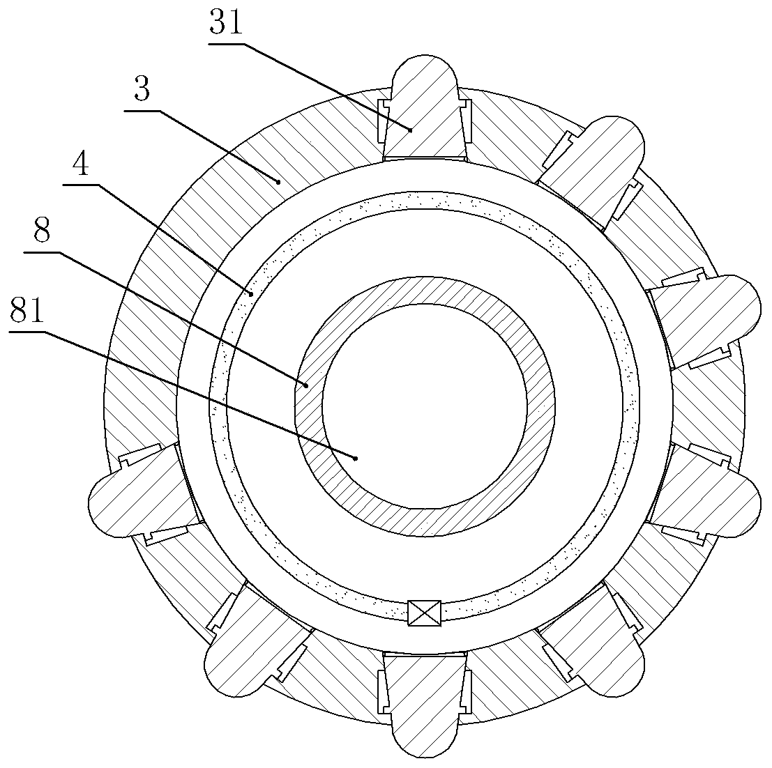
[0045] On the basis of Example 1, such as image 3 As shown, the sleeve 3 in this embodiment is provided with an inner rod 8, and the two ends of the inner rod 8 run through the two ends of the elastic airbag 4. The elastic airbag 4 in this embodiment covers the outer wall of the inner rod 8. Specifically, the elastic The two ends of the airbag 4 are glued on the inner rod 8 . The inner rod 8 is provided with a condensation chamber 81, and the left and right ends of the inner rod 8 are glued with pipes.

[0046] When the positioning device for blood drawing in this embodiment is in use, the pipeline connected to one end of the inner cylinder can be communicated with external refrigeration equipment such as an air conditioner, and low-temperature gas can be introduced into the inner rod 8, and the low-temperature gas can be used after entering the inner rod 8. The temperature of the inner rod 8 and the sleeve 3 decreases, and then it is discharged from the other end of the inn...


PUM


Abstract

The invention relates to the field of medical instruments, and particularly discloses a positioning device for blood drawing. The positioning device comprises a positioning rod, a positioning plate and a limiting unit, the positioning plate is opposite to the needle head, and the positioning rod is located between the positioning plate and the needle head and perpendicular to the moving directionof the needle head; the limiting unit is located on the side, away from the needle head, of the positioning rod and comprises a limiting plate capable of sliding towards the side close to the needle head and a driving piece used for driving the limiting plate to slide, and the limiting plate is opposite to the positioning rod. According to the positioning device for blood drawing, the arm of a patient can be fixed, so that a needle head can conveniently position a blood vessel.

Description

technical field [0001] The invention relates to the field of medical instruments, in particular to a positioning device for blood drawing. Background technique [0002] When seeking medical treatment in a hospital, drawing blood for examination is a commonly used means of examination. When there are a large number of people seeking medical treatment, the workload of the medical staff responsible for drawing blood and performing laboratory tests is relatively large, and due to the limited number of medical staff, the medical staff responsible for drawing blood Due to the limited number of personnel, the workload of the medical staff in charge of drawing blood is heavy; and when some medical staff are in charge of drawing blood, the number of medical staff in charge of testing decreases accordingly, and it takes a certain amount of time to test blood, so patients It is usually necessary to wait for a long time to receive the results, which will undoubtedly prolong the patient'...

Claims


Application Information

Patent Timeline
Patent Type & Authority Applications(China)
IPC IPC(8): A61B5/15A61M35/00
CPCA61M35/00A61B5/150328A61B5/150007A61B5/70
Inventor 江雪梅张艳玲
Owner THE FIRST AFFILIATED HOSPITAL OF ARMY MEDICAL UNIV
Why Eureka
Try Eureka