
A switchable inferior vena cava thrombus filter

A filter and vena cava technology, applied in the medical field, can solve problems such as thrombus leaking into pulmonary vessels, difficulty in opening, and arterial embolism in patients, so as to avoid passing through the filter device, avoid vascular embolism, and ensure the filtering effect Effect

Inactive Publication Date: 2021-07-09
JILIN UNIV
View PDF5 Cites 0 Cited by
  • Summary
  • Abstract
  • Description
  • Claims
  • Application Information

AI Technical Summary

Problems solved by technology

[0002] The vena cava filter is a medical filter. Pulmonary embolism is an emergency with high clinical morbidity and mortality. In the United States, the annual number of symptomatic pulmonary embolism cases reaches 570,000 to 630,000, of which 200,000 lead to death. Although systemic anticoagulant therapy can achieve some curative effect, there are still 3-20% of recurrent pulmonary embolism, and anticoagulant therapy itself also has 26% complications, of which 5-12% are fatal complications; some patients cannot accept anticoagulant Coagulation therapy, such as acute bleeding, peptic ulcer, primary or metastatic tumor, pregnancy, before surgical treatment, etc.
[0003] After the existing filter is injected into the blood vessel, it usually achieves the fixation effect by expanding its own metal elastic force. However, the fixation effect is often not ideal, and it is easy to tilt inside the blood vessel, resulting in the failure of its filtering function, and the existing filter is injected into the blood vessel. It is also prone to difficulty in opening, resulting in the failure of the filter device to work normally, and the existing filter device has only one layer of filter mesh, which has poor filtering effect and easily causes thrombus to leak into the pulmonary blood vessels, thus causing the patient's risk of arterial embolism

Method used


Image

  • A switchable inferior vena cava thrombus filter
  • A switchable inferior vena cava thrombus filter
  • A switchable inferior vena cava thrombus filter

Examples


Embodiment Construction

[0022] The following will clearly and completely describe the technical solutions in the embodiments of the present invention with reference to the accompanying drawings in the embodiments of the present invention. Obviously, the described embodiments are only some, not all, embodiments of the present invention. Based on the embodiments of the present invention, all other embodiments obtained by persons of ordinary skill in the art without making creative efforts belong to the protection scope of the present invention.

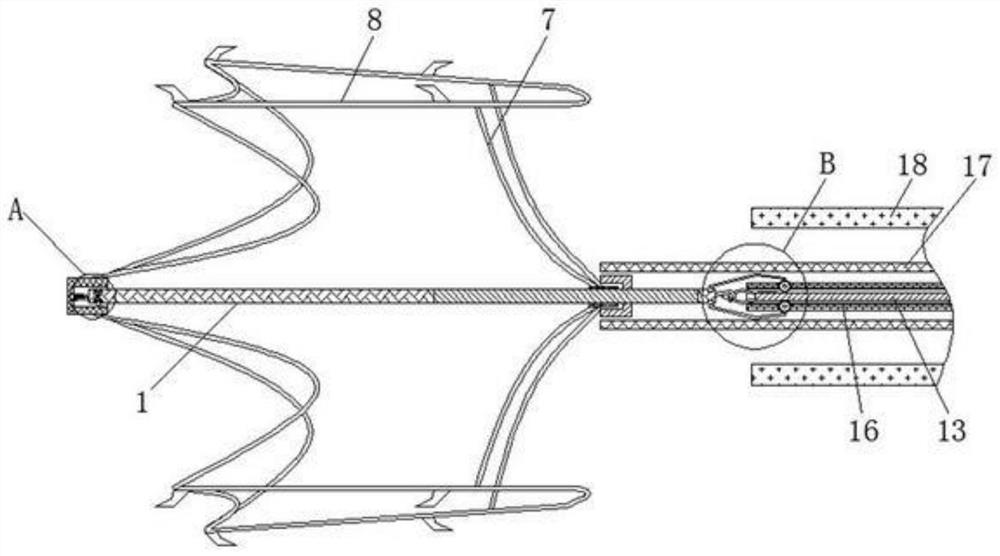
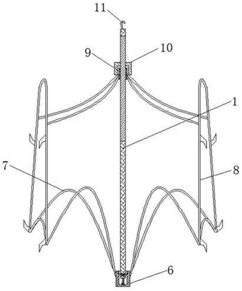
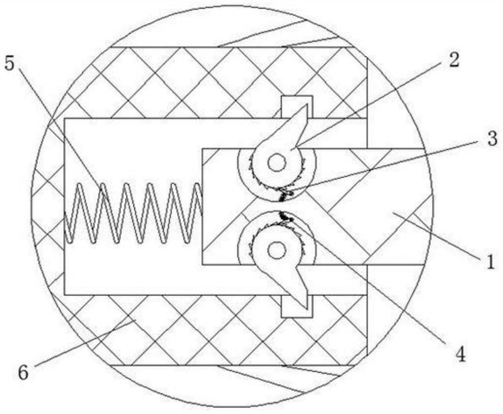
[0023] see Figure 1 to Figure 4 As shown, a convertible inferior vena cava thrombosis filter includes a support rod 1, a positioning block 2, a limiting claw 3, a limiting spring 4, a supporting spring 5, a fixing block 6, a mesh rod 7, a positioning rod 8, a positioning Cover 9, threaded sleeve 10, grapple hook 11, catch cover 12, pull bar 13, gear 14, stop bar 15, cover bar 16, fixed bar 17, receive object bar 18.

[0024] The positions and connections of ...


PUM


Abstract

The invention relates to the field of medical technology, and discloses a convertible inferior vena cava thrombus filter, which includes a support rod, a positioning block is movably connected to the inside of the support rod, and a positioning block is movably connected to a limiting claw on the outside of the positioning block. The outside of the limit claw is fixedly connected with a limit spring, the outside of the support rod is movably connected with a support spring, the outside of the support spring is movably connected with a fixed block, and the outside of the fixed block is fixedly connected with a net rod. The outside of the mesh pole is fixedly connected with a positioning rod. Through the cooperation of the support rod, fixed block, positioning rod, positioning sleeve and threaded sleeve, the expansion effect of the support rod plus the positioning rod can be achieved, ensuring the stability of the tension of the positioning rod. , and the fixed claws provided by the positioning rod can effectively ensure the stability of the device in the venous blood vessel, thereby ensuring the normal use of the device, thereby ensuring the filtering effect of thrombus and avoiding the risk of vascular embolism in patients.

Description

technical field [0001] The invention relates to the field of medical technology, in particular to a switchable inferior vena cava thrombus filter. Background technique [0002] The vena cava filter is a medical filter. Pulmonary embolism is an emergency with high clinical morbidity and mortality. In the United States, the annual number of symptomatic pulmonary embolism cases reaches 570,000 to 630,000, of which 200,000 lead to death. Although systemic anticoagulant therapy can achieve some curative effect, there are still 3-20% of recurrent pulmonary embolism, and anticoagulant therapy itself also has 26% complications, of which 5-12% are fatal complications; some patients cannot accept anticoagulant Coagulation therapy, such as acute bleeding, peptic ulcer, primary or metastatic tumor, pregnancy, before surgical treatment, etc. [0003] After the existing filter is injected into the blood vessel, it usually achieves the fixation effect by expanding its own metal elastic fo...

Claims


Application Information

Patent Timeline
Patent Type & Authority Patents(China)
IPC IPC(8): A61F2/01
CPCA61F2/01
Inventor 史媛媛李金秋陈雪田莹李春颖韩敬华刘文平许崴崴高玉霞陈立
Owner JILIN UNIV
Learn More