Tool changing mechanism provided with device capable of controlling pipe cutting machine feeding speed through pressure feedback

A technology of feedback control and feed speed, which is applied in the direction of cutters, pipe shearing devices, and shearing devices used in shearing devices, can solve the problems of low cooling efficiency and inconvenient blade replacement, and achieve increased cooling effect and increased Cooling effect, effect of prolonging working life

Pending Publication Date: 2020-08-04
张家港市越泰精密机械有限公司
View PDF1 Cites 0 Cited by
  • Summary
  • Abstract
  • Description
  • Claims
  • Application Information

AI Technical Summary

Problems solved by technology

[0004] The purpose of the present invention is to provide a tool changing mechanism with a pressure feedback control device for cutting the knife feed speed of the pipe cutting machine, so as to solve the problem that the blade changing mechanism of the existing part of the pipe cutting machine proposed in the above-mentioned background technology is inconvenient to replace, and The cooling efficiency of some existing pipe cutting machine tool change mechanisms is not high

Method used


Image

  • Tool changing mechanism provided with device capable of controlling pipe cutting machine feeding speed through pressure feedback
  • Tool changing mechanism provided with device capable of controlling pipe cutting machine feeding speed through pressure feedback
  • Tool changing mechanism provided with device capable of controlling pipe cutting machine feeding speed through pressure feedback

Examples


Embodiment Construction

[0027] The following will clearly and completely describe the technical solutions in the embodiments of the present invention with reference to the accompanying drawings in the embodiments of the present invention. Obviously, the described embodiments are only some, not all, embodiments of the present invention. Based on the embodiments of the present invention, all other embodiments obtained by persons of ordinary skill in the art without making creative efforts belong to the protection scope of the present invention.

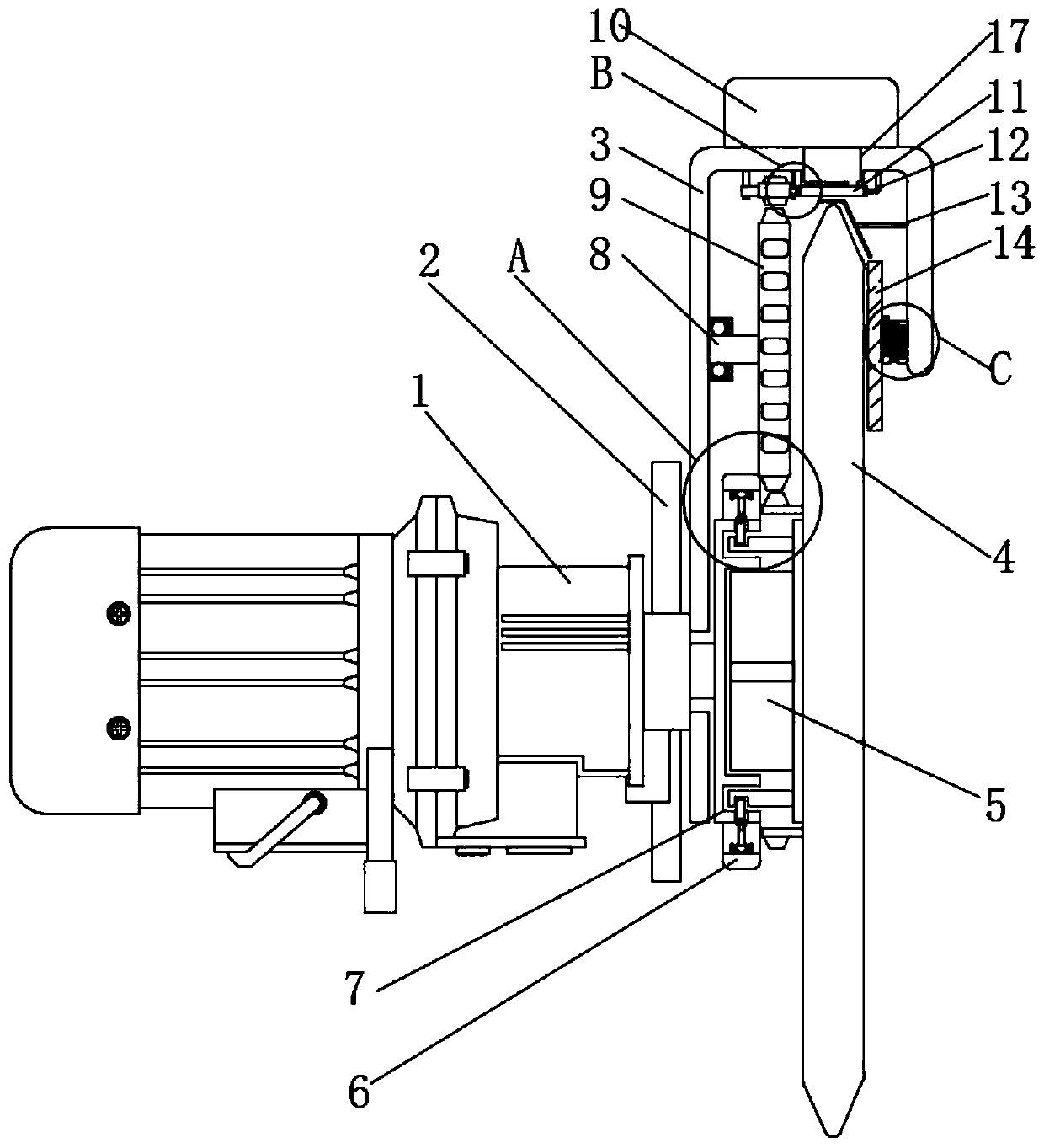
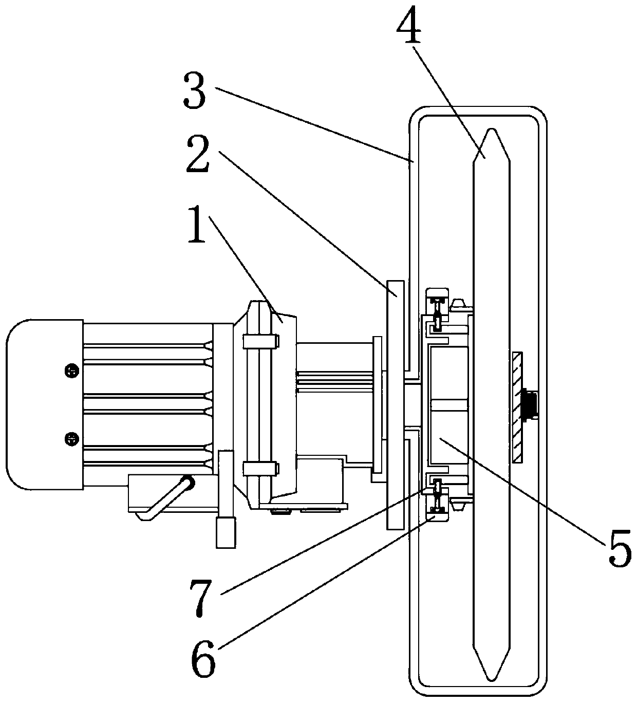
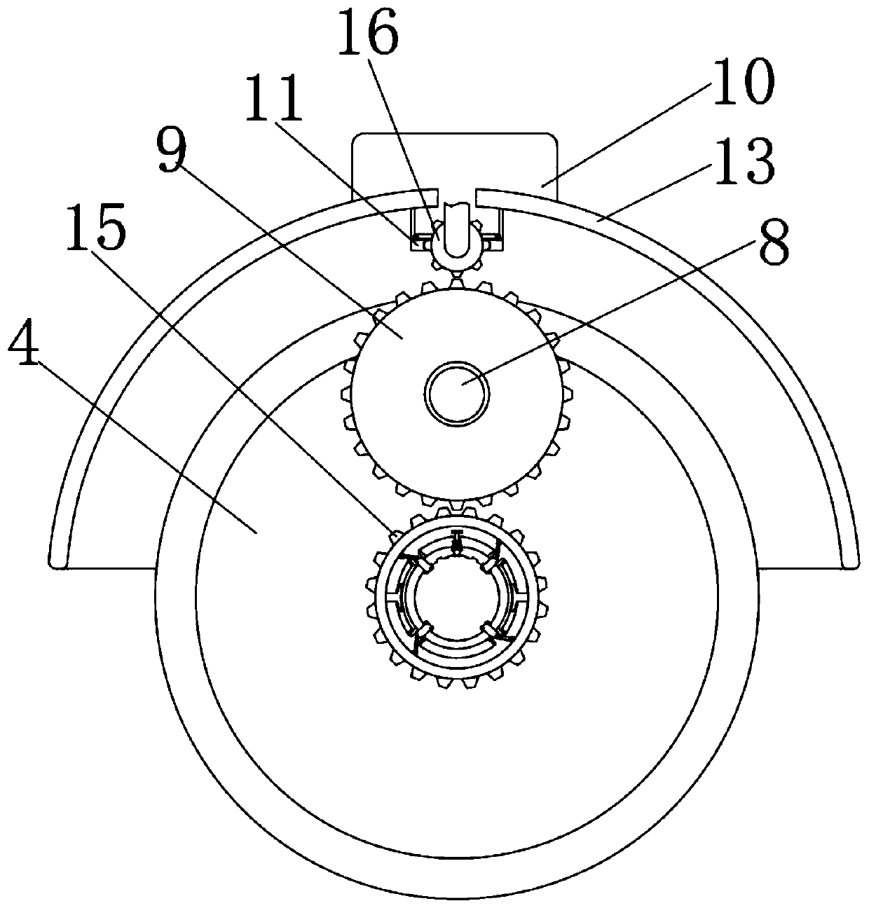
[0028] see Figure 1-9 , an embodiment provided by the present invention: a tool changing mechanism with a pressure feedback control device for feeding speed of a pipe cutter, including a servo motor 1, a support arm 2, a protective jacket 3 and a cutting blade 4, one of the servo motors 1 The side surface is sleeved with a support arm 2, one side of the servo motor 1 is connected with a protective jacket 3, and the top of the protective jacket 3 is connected ...


PUM


Abstract

The invention discloses a tool changing mechanism provided with a device capable of controlling pipe cutting machine feeding speed through pressure feedback. The tool changing mechanism comprises a servo motor, a support arm, a protective sleeve and a cutting blade; the support arm is connected with the surface of one side of the servo motor in a sleeving manner; the protective shell is connectedwith one side of the servo motor; a water storage box is connected with the top end of the protective shell; a first water storage groove is connected with the bottom end of the water storage box; a first seal plate is connected with the bottom end of the first water storage groove; a first support frame is connected with one side of the first seal plate and is connected with the inner wall of theprotective shell; an internal carrying groove is formed in the first seal plate; the inner wall of the internal carrying groove is propped against a semi gear; and one side of the semi gear is connected with a first carrying rod. According to the tool changing mechanism, a first connecting block and a first connecting rod are arranged to conveniently detach a first fixture block; and in addition,the tool changing mechanism is provided with a cooling plate and the first seal plate to effectively improve the cooling effect to the cutting blade.

Description

technical field [0001] The invention relates to the technical field of pipe cutting machines, in particular to a tool change mechanism with a pressure feedback control device for feeding speed of pipe cutting machines. Background technique [0002] The automatic pipe cutting machine is suitable for cutting steel pipes, stainless steel pipes, copper pipes, aluminum pipes and other pipes. Generally, it can meet the occasions of mass production in petroleum, metallurgy, bearings and other industries. However, the pipe cutting machine The core is the cutting blade, and the long-term pipe cutting will cause the cutting blade to wear out. At this time, it is necessary to use the tool change mechanism to replace and maintain the cutting blade. [0003] For example, the publication number: CN110605614A, discloses a method and device for controlling the feed speed of a pipe cutting machine based on pressure feedback, including the following steps: preset the pressure value based on t...

Claims


Application Information

Patent Timeline
IPC IPC(8): B23D21/00B23D35/00B23D33/00B23Q11/10
CPCB23D21/00B23D33/00B23D35/004B23Q11/10
Inventor 阳江斌吴士化
Owner 张家港市越泰精密机械有限公司
Why Eureka
Try Eureka