Method for driving seesaw flywheel power machine to operate by utilizing gravity, magnetic force and buoyancy

A buoyancy-driven, seesaw technology, which is applied in the direction of mechanisms, engines, and engine components that generate mechanical power, can solve the problems of high energy consumption, environmental pollution, and high operating costs, and achieves high power utilization, high power conversion, and simple structure. Effect

Inactive Publication Date: 2020-08-04
郭志坚
View PDF0 Cites 0 Cited by
  • Summary
  • Abstract
  • Description
  • Claims
  • Application Information

AI Technical Summary

Problems solved by technology

[0002] Mechanical operation, such as the seesaw flywheel power machine (application number or patent number: 2018110847370), requires an external driving force for the seesaw up and down movement. At present, the driving of mechanic

Method used


Image

  • Method for driving seesaw flywheel power machine to operate by utilizing gravity, magnetic force and buoyancy
  • Method for driving seesaw flywheel power machine to operate by utilizing gravity, magnetic force and buoyancy
  • Method for driving seesaw flywheel power machine to operate by utilizing gravity, magnetic force and buoyancy

Examples


Embodiment 1

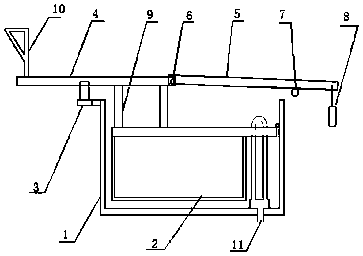
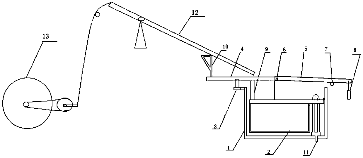
[0030] see figure 1 and figure 2 , a kind of method that utilizes gravity, magnetic force and buoyancy to drive seesaw flywheel power machine operation, and its method comprises the following steps.

[0031] (1) A water tank (1) with a built-in automatic water tank (11) is set, and the height of the siphon of the automatic water tank (11) is the same as or slightly higher than the height of the upper plane of the buoyancy tank (2).

[0032] (2) A buoyant tank (2) is set in the water tank (1), and the buoyant tank (2) can float and rotate around its support rotation point fixed on the wall of the water tank (1).

[0033] (3) A push rod (4) with a magnetic touch switch (3) is erected on the buoyant tank (2), and the push rod (4) is fixed on the buoyant tank (2) through a bracket (9) On the upper platform of the upper platform, which is horizontal to the water tank (1), one end protrudes out of the tank body, and the protruding top end is provided with a pennant-shaped support...

Embodiment 2

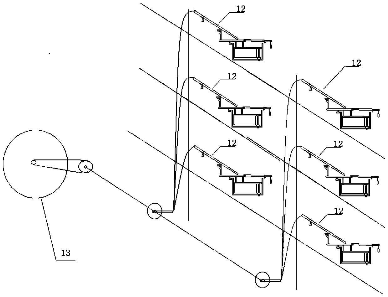
[0038] see figure 2 and image 3 , this example is the expansion of the above-mentioned embodiment 1, the tower-type combined operation method, and the method includes the following steps.

[0039] 1. The water tank described in Embodiment 1 of the method of the present invention, including a complete set of driving components, is stacked and placed in a well-shaped tower structure.

[0040] 2. Corresponding to each layer of driving components, set up a separate seesaw (12).

[0041] 3. Connect the drain pipe of the upper water tank to the water inlet of the lower water tank.

[0042] Water injection in the upper water tank pushes the corresponding seesaw (12) to move, and drives the inertial flywheel (13) of the seesaw flywheel power machine to rotate.

[0043] When the driving stroke of the upper layer is completed, the water tank is drained into the lower water tank, and the lower water tank relays to push the corresponding seesaw (12) to move, so that the inertial flyw...


PUM


Abstract

The invention discloses a method for driving a seesaw flywheel power machine to operate by utilizing gravity, magnetic force and buoyancy. The seesaw flywheel power machine is another invention (application number or patent number: 2018110847370). A floating box (2) capable of rotating along with rising and falling of the water tank (1) on the water surface is arranged, a push rod (4) with a magnetic touch switch (3) is erected on the floating box (2), the magnetic force of the magnetic touch switch (3) can lock the floating box (2) so that the floating box (2) cannot float up as the water surface rises, until a set water surface height is reached, the magnetic force is released, the floating box (2) and the push rod (4) begin to rapidly rotate, and thus a seesaw (12) of the seesaw flywheel power machine is pushed to move rapidly; a counterweight rod (5) is arranged to be connected with the push rod (4) through a rotating shaft (6); and when the floating box (2) rapidly rotates and ascends, the counterweight rod (5) drops rapidly to generate acceleration gravity amplification and enhance the continuous driving force of the push rod (4).

Description

technical field [0001] The present invention relates to a technology for driving mechanical movement by using gravity, magnetic force and buoyancy, especially a method for driving a seesaw flywheel power machine (application number or patent number: 2018110847370) by using gravity, magnetic force and buoyancy. Background technique [0002] Mechanical operation, such as the seesaw flywheel power machine (application number or patent number: 2018110847370), requires an external driving force for the seesaw up and down movement. At present, the driving of mechanical operation is basically driven by converting water flow energy and heat energy into electrical energy. Using these methods consumes A large amount of energy, high operating costs, polluting the environment and non-renewable energy. Contents of the invention [0003] To solve this problem, the present invention discloses a method for driving the seesaw flywheel power machine by using gravity, magnetic force and buoy...

Claims


Application Information

Patent Timeline
IPC IPC(8): F03G3/00F03G7/00F03B17/02H02N11/00
CPCF03B17/02F03G3/00F03G7/00H02N11/008Y02E10/20
Inventor 郭志坚
Owner 郭志坚
Why Eureka
Try Eureka