
Light-emitting device and vehicle lamp applying same

A light-emitting device and car lamp technology, which is applied in the direction of headlights, signal devices, lighting devices, etc., can solve the problems of low optical power density, difficult light source installation and heat dissipation, etc.

Pending Publication Date: 2020-08-04
YLX INC
View PDF6 Cites 1 Cited by
  • Summary
  • Abstract
  • Description
  • Claims
  • Application Information

AI Technical Summary

Problems solved by technology

[0004] The present application provides a light emitting device and its application to solve the problems of low optical power density and difficult installation and heat dissipation of the virtual filament in the prior art

Method used


Image

  • Light-emitting device and vehicle lamp applying same
  • Light-emitting device and vehicle lamp applying same

Examples


Embodiment Construction

[0024] The following will clearly and completely describe the technical solutions in the embodiments of the application with reference to the drawings in the embodiments of the application. Apparently, the described embodiments are only some of the embodiments of the application, not all of them. Based on the embodiments in this application, all other embodiments obtained by persons of ordinary skill in the art without making creative efforts belong to the scope of protection of this application.

[0025] It should be noted that if there are directional indications (such as up, down, left, right, front, back...) in the embodiment of the present application, the directional indications are only used to explain the position in a certain posture (as shown in the accompanying drawings). If the specific posture changes, the directional indication will also change accordingly.

[0026] In addition, if there are descriptions involving "first", "second", etc. in the embodiments of the...


PUM


Abstract

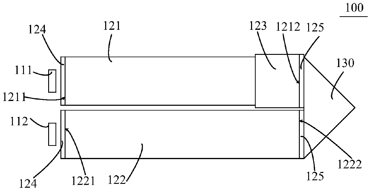
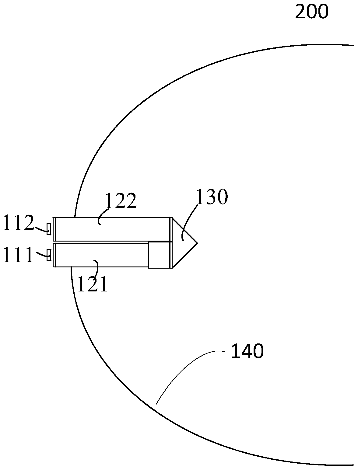
The invention discloses a light-emitting device and a vehicle lamp applying the same. The light-emitting device comprises two light sources, a first light conductor, a second light conductor and lightguide elements, wherein the first light conductor and the second light conductor are arranged side by side; the first light conductor comprises a first light incident surface and a first tail end surface; the second light conductor comprises a second light incident surface and a second tail end surface, the first light incident surface and the first tail end surface are arranged on the same side,and the first tail end surface and the second tail end surface are arranged on the same side; two light sources are respectively arranged on the first light incident surface and the second light incident surface; the light guide elements are arranged on the first tail end surface and the second tail end surface; the first light conductor comprises a light emitting part, and the light emitting part is arranged on the second tail end face close to the first light conductor. According to the light-emitting device, the two light conductors arranged side by side and the light guide elements are arranged to form two light paths, so that light emitted by the two light sources is conducted and gathered to the light emitting part to be emitted, the luminous flux of the light emitting part can be improved, and meanwhile the light expansion amount of the whole light-emitting device is reduced.

Description

technical field [0001] The present application relates to the technical field of lighting equipment, in particular to a light emitting device and a car light using the same. Background technique [0002] LED light source has the advantages of energy saving, environmental protection and long life, but the existing LED light source is a one-sided light emitting body, and its luminous characteristics are different from those of traditional car lamp filaments such as halogen filaments or tungsten filaments, making it impossible to directly replace traditional filaments. A virtual filament is proposed in the prior art, which guides the light emitted by the LED light source into a photoconductor to simulate the luminous characteristics of the traditional filament, so that it can directly replace the traditional filament and be used in the reflective bowl. [0003] The existing virtual filament exists mainly because the brightness of the illumination light pattern formed when it is...

Claims


Application Information

Patent Timeline
IPC IPC(8): F21S41/24F21S41/20F21S43/235F21S43/20F21W102/00F21W103/00F21W107/00F21Y115/10F21Y115/30
CPCF21S41/24F21S41/285F21S43/235F21S43/26F21W2102/00F21W2103/00F21W2107/00F21Y2115/10F21Y2115/30F21S41/20F21S43/20
Inventor 张贤鹏刘莹莹李乾
Owner YLX INC
Learn More