
Directional air transmission device and air disinfection system for prevention and control of pathogenic microorganisms in sick area

A technology of pathogenic microorganisms and directional transmission, which is applied in the field of air directional transmission devices and air disinfecting systems in pathogenic microorganisms prevention and control wards, which can solve the problems of unorganized virus diffusion, poor ventilation, harmful gases, etc., and reduce the survival time of viruses , low cost, and the effect of avoiding pollution

Active Publication Date: 2020-08-04
XI'AN UNIVERSITY OF ARCHITECTURE AND TECHNOLOGY
View PDF6 Cites 11 Cited by
  • Summary
  • Abstract
  • Description
  • Claims
  • Application Information

AI Technical Summary

Problems solved by technology

[0005] In view of the above problems, the purpose of the present invention is to provide an air directional transmission device and an air disinfecting system for pathogenic microorganism prevention and control wards. Through reasonable configuration of the component structure, a directional clean air belt is formed and sent directly to the breathing area of ​​the personnel, so as to solve the problem of hospitalization. Harmful gases, unorganized spread of viruses and pollution in the ward, solve the problem that the HVAC system adjustment method can accurately meet the standards and the ventilation effect is poor when the air quality requirements inside the hospital change

Method used


Image

  • Directional air transmission device and air disinfection system for prevention and control of pathogenic microorganisms in sick area
  • Directional air transmission device and air disinfection system for prevention and control of pathogenic microorganisms in sick area
  • Directional air transmission device and air disinfection system for prevention and control of pathogenic microorganisms in sick area

Examples


Embodiment 1

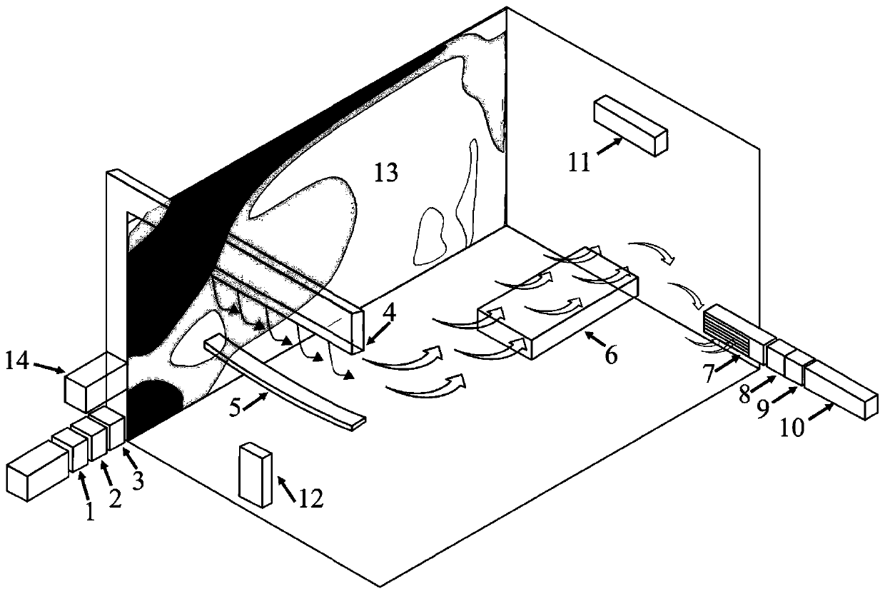
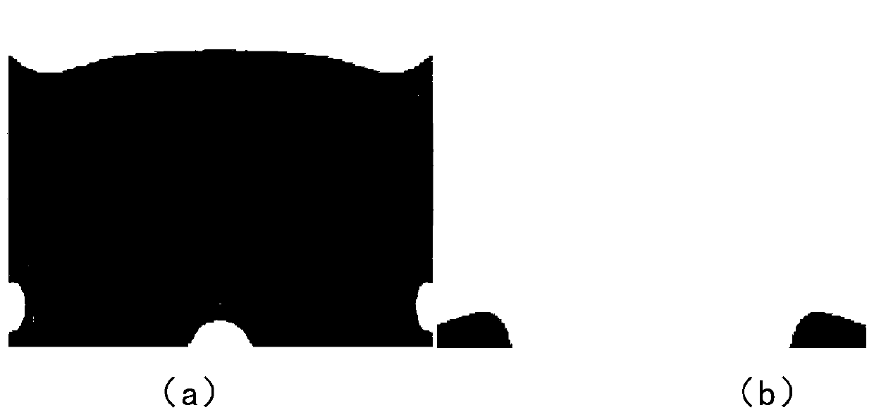
[0035] Compared with the velocity distribution of deflectors with different radians, such as figure 2 As shown, the traditional deflector is a straight baffle without curvature. When the deflector produces different radians of upward protrusion and downward depression, the resulting diversion effect will change and affect the airflow organization form. Such as figure 2 (b) is the velocity distribution nephogram in the ward formed by the curved deflector 5 . The arc deflector 5 of the present invention is concave downwards, and the curved radian is Compared with other curved radians, it can be found that under this downward concave radian, the air outlet speed can meet the wind speed requirements inside the ward, and the jet flow area can reach the patient's breathing area, which shows that the air directional transmission technology in the pathogenic microorganism prevention and control ward of the present invention The curved deflector has a good improvement effect.

Embodiment 2

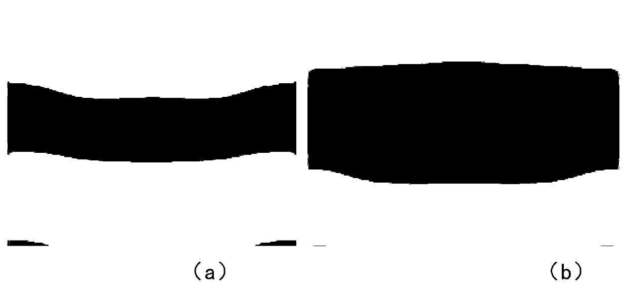
[0037] The present invention is compared with the airflow organization of traditional ward interior ventilation, as image 3 As shown, it is found that the wind coverage of the traditional ward ventilation system is poor, the wind speed does not meet the requirements, etc., and the fresh air is mixed with the polluted air in the room. After the vertical wall-attached jet is added to the traditional ward, it is drained through the arc-shaped deflector, and at the same time merged with the air flow of the air purification device. The air directional transmission technology in the pathogenic microorganism prevention and control ward of the present invention sends the air flow to the designated area in an organized manner, that is, It shows that the air directional transmission technology in the pathogenic microorganism disease area has a good air supply effect.

Embodiment 3

[0039] Such as Figure 5 As shown, for the purification coating smearing wall 13 wind speed area distribution streamline diagram, 6 typical curves will clean the coating coating wall 13 is divided into different 4 areas; Wherein area one is by typical curve 1, typical curve 2, typical curve 3 and Typical curve 4 is surrounded, area 2 is surrounded by typical curve 1, typical curve 2, typical curve 3, typical curve 4 and typical curve 5, area 3 is surrounded by typical curve 5 and typical curve 6, and area 4 is surrounded by typical curve 6 surrounded.

[0040] The regional distribution of wind speed is determined by the wind speed proportional coefficient of each region, and the wind speed proportional coefficient is the ratio of the regional wind speed to the wind speed of the air supply outlet of the slit Among them, V x Be the regional wind speed, and the regional wind speed is the wind speed within 10 centimeters of the wall 13 surface where the purification coating is ...


PUM


Abstract

The invention discloses a directional air transmission device and an air disinfection system for prevention and control of pathogenic microorganisms in a sick area. The device comprises an air-cooledheat pump fresh air unit module, an ultraviolet disinfection module and an air purification pipe connected in sequence outside the sick area, also comprises a slot air supply outlet that is located above the side wall in the sick area, is connected to the air purification pipe and supplies air vertically downward, and also comprises an arc-shaped deflector located below the slot air supply outlet,wherein the arc-shaped deflector is recessed downward, the curved arc also comprises a negative pressure exhaust device located below the opposite wall of the side wall, and clean fresh air is outputthrough the slot air supply outlet to the arc-shaped deflector for deflecting and conveying, and then is filtered and discharged by the negative pressure exhaust device. Through the reasonable setting of the component structure, a directional clean air belt is formed and sent directly to the breathing area of personnel, which solves the unorganized spread and pollution of harmful gases and viruses in the hospital ward, and solves the problems that the HVAC system can accurately meet the standards when the air quality requirements change in the hospital, and that the ventilation effect is poor.

Description

technical field [0001] The invention relates to the field of ventilation and air conditioning, in particular to an air directional transmission device and an air disinfecting system for pathogenic microorganism prevention and control wards. Background technique [0002] Buildings with special functions, especially hospital wards, treatment rooms, and doctor's duty rooms that require high indoor air quality, have different HVAC system designs from heavily polluted areas to semi-polluted areas to clean areas. Organized ventilation in hospital buildings is extremely important. The core of organized ventilation is to control ventilation: control the volume of ventilation, control the time of ventilation, and control the direction of indoor airflow. In a hospital building where patients and medical staff are concentrated and saturated: first, it can provide fresh air, remove polluted air, and ensure the air quality in the space; second, it can control the air gradient pressure di...

Claims


Application Information

Patent Timeline
Patent Type & Authority Applications(China)
IPC IPC(8): F24F5/00F24F3/16F24F13/02F24F13/072F24F13/08E04F13/02
CPCE04F13/02F24F5/0007F24F13/02F24F13/072F24F13/081F24F8/192F24F8/22F24F8/30Y02A50/20
Inventor 侯立安李安桂张林吴明红高然
Owner XI'AN UNIVERSITY OF ARCHITECTURE AND TECHNOLOGY
Learn More