Light filtering device, camera and light-emitting light source
A filter device and electrochromic device technology, applied in the optical field, can solve the problems of equipment mechanical structure damage, inconvenient expenditure cost, increase user operation, etc., to achieve the effect of protection, reduce expenditure cost, and strengthen structural stability
- Summary
- Abstract
- Description
- Claims
- Application Information
AI Technical Summary
Problems solved by technology
Method used
Image
Examples
Embodiment 1
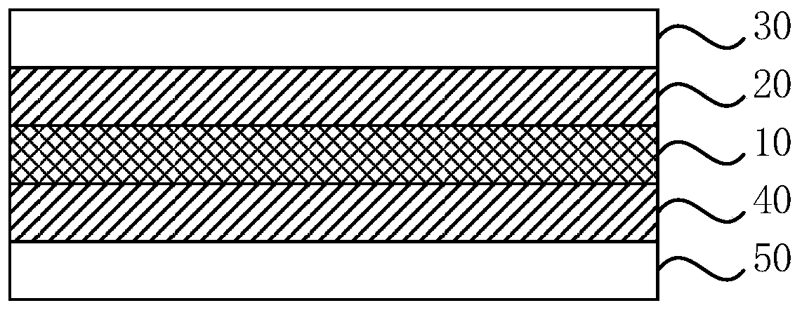
[0039] Embodiment 1 of the present invention provides a filter device, which includes: an electrochromic device; figure 1 As shown, the electrochromic device includes a stacked electrochromic layer 10, a first stacking layer 20, and a first substrate 30; wherein, the electrochromic layer 10 includes: a first conductive substrate, a color-changing material layer, and a stacked stacked layer in sequence. second conductive substrate. Wherein, the color-changing material layer is a layer of adjustable transmittance composed of one or more layers of liquid or solid materials, such as polymer dispersed liquid crystal (Polymer Dispersed Liquid Crystal, PDLC) glass, suspended particle device (Suspended Particle Device, SPD ) and electrochromic (Electrochromic, EC) and other types.
[0040] Specifically, EC is a phenomenon in which the optical properties (reflectivity, transmittance, absorbance, etc.) of a material undergo a stable and reversible color change under the action of an ap...
Embodiment 2
[0056] Embodiment 2 of the present invention provides a filter device. The technical solution of this embodiment is further refined on the basis of the technical solution of the above embodiment, optionally, such as Figure 4 As shown, the surface on the first substrate 30 away from the first stacking layer 20 is a curved surface, Figure 4 The optimization based on the filter device including the second stacking layer 40 and the second substrate 50 is shown as an example.
[0057] Specifically, when the filter device provided in this embodiment is applied, the light can be incident from the second substrate 50 and exit from the first substrate 30 after the light filtering is completed. The first substrate 30 includes two surfaces that are close to and far from the first stacking layer 20 , and the light is specifically emitted from the surface of the first substrate 30 that is far away from the first stacking layer 20 . When the surface away from the first superimposed laye...
Embodiment 3
[0060] Embodiment 3 of the present invention provides a filter device. The technical solution of this embodiment is further refined on the basis of the technical solution of the above-mentioned embodiment. Optionally, the electrochromic layer 10 includes a plurality of electrochromic regions arranged in tiles, and the filter device adjusts each electrochromic region separately. The transmittance of the electrochromic regions; the color-changing material layers of the plurality of electrochromic regions include at least two materials.
[0061]Specifically, the cross-section of the electrochromic layer 10 can be of any shape, and all the electrochromic regions included on the electrochromic layer 10 can fill the entire electrochromic layer 10, or only occupy a part of the region, and at the same time, The multiple electrochromic regions can be adjacent or non-adjacent. When all the electrochromic regions only occupy a part of the electrochromic layer 10, a fly-eye lens can be a...
PUM
| Property | Measurement | Unit |
|---|---|---|
| thickness | aaaaa | aaaaa |
| thickness | aaaaa | aaaaa |
| thickness | aaaaa | aaaaa |
Abstract
Description
Claims
Application Information
 - R&D
- Intellectual Property
- Life Sciences
- Materials
- Tech Scout
- Unparalleled Data Quality
- Higher Quality Content
- 60% Fewer Hallucinations
Browse by: Latest US Patents, China's latest patents, Technical Efficacy Thesaurus, Application Domain, Technology Topic, Popular Technical Reports.
© 2025 PatSnap. All rights reserved.Legal|Privacy policy|Modern Slavery Act Transparency Statement|Sitemap|About US| Contact US: help@patsnap.com


