Assembled cervical interbody fusion cage

An intervertebral fusion device and modular technology, applied in the field of modular cervical intervertebral fusion devices

Pending Publication Date: 2020-08-07
卿培东
View PDF6 Cites 1 Cited by
  • Summary
  • Abstract
  • Description
  • Claims
  • Application Information

AI Technical Summary

Problems solved by technology

However, bone grafts as a single support do

Method used


Image

  • Assembled cervical interbody fusion cage
  • Assembled cervical interbody fusion cage
  • Assembled cervical interbody fusion cage

Examples


Embodiment 1

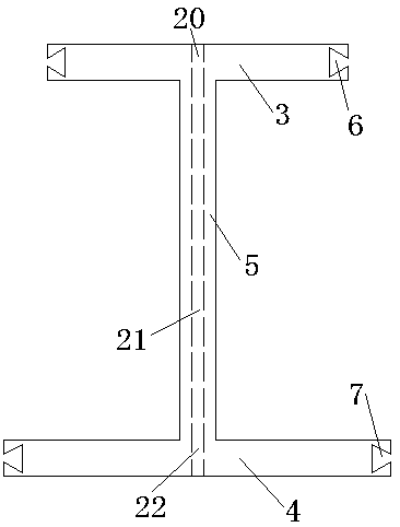
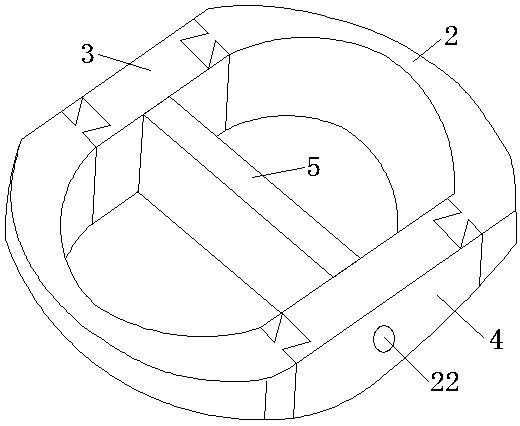
[0069] The cervical intervertebral fusion device of this embodiment includes an I-shaped support and a side wall connector; wherein, the I-shaped support mainly functions as a support, and the side wall connector is mainly used to form a bone graft cavity. In this embodiment, the I-shaped support includes a first support rod, a second support rod, and a longitudinal connecting rod. The rod, the longitudinal connecting rod are connected with the second support rod to form an I shape. In order to simplify the drawings, the applicant in figure 2 It is represented by a straight line; in actual application, the shape and length of the first support rod and the second support rod can be changed accordingly according to actual needs. Preferably, the first support rod, the longitudinal connecting rod and the second support rod are integrally formed.

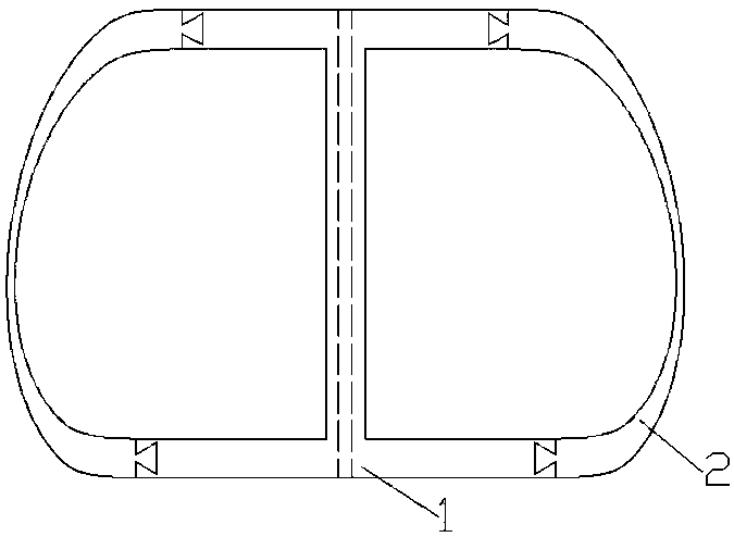
[0070] like figure 1 As shown, the side wall connectors are a group, the cross section of the side wall connectors along the horiz...


PUM


Abstract

The invention discloses an assembled cervical interbody fusion cage, and belongs to the field of spine fusion instruments. The device comprises an H-shaped supporting piece used for providing a supporting function and side wall connecting pieces, wherein the H-shaped supporting piece comprises a first supporting rod, a second supporting rod and a longitudinal connecting rod, the two ends of the first supporting rod are each provided with a first connecting piece, and the two ends of the second supporting rod are each provided with a second connecting piece; the two ends of the longitudinal connecting rod are connected with the first supporting rod and the second supporting rod into a whole, and an I-shaped supporting piece formed by the first supporting rod, the longitudinal connecting rodand the second supporting rod is in an H-like shape. Practical application results show that on the basis of the new structural design, uncovertebral joint bone grafting can be achieved, the fusion rate can be effectively increased, the bone grafting side uncovertebral joint fusion rate is higher than the non-bone-grafting side uncovertebral joint fusion rate, so that remarkable progressive significance is achieved. Meanwhile, based on the improvement of the structure, corresponding choices can be made for different patients, so that the optimal clinical effect and the maximum fusion are ensured.

Description

technical field [0001] The invention relates to the field of medical instruments, in particular to the field of spinal fusion instruments, in particular to a modular cervical intervertebral fusion device. Background technique [0002] Spinal fusion techniques have been used for decades to treat a variety of spinal conditions. Initial fusion techniques involved extensive muscle release, autologous bone grafting, and prolonged immobilization on a traction table. Since the development of spinal internal fixation technology, the success rate of spinal fusion has been improved, shortening the recovery time of patients, and leaving more options for surgical treatment. In order to reduce the failure rate of simple posterior spinal fusion and internal fixation, the concept of anterior column support fusion has gradually emerged. Initially, bone grafts were placed in the intervertebral space through an anterior-posterior approach to better improve blood supply to the affected area,...

Claims


Application Information

Patent Timeline
IPC IPC(8): A61F2/44
CPCA61F2/4455A61F2002/30131A61F2002/30182A61F2002/30331A61F2310/00005
Inventor 卿培东刘利曹云邓海涛李明凡
Owner 卿培东
Why Eureka
Try Eureka