Fire-fighting equipment

A technology for fire-fighting equipment and body, applied in the field of fire-fighting equipment, can solve the problems of reducing the service life of hoses, affecting the use of fire-fighting equipment, delaying fire-fighting time, etc., and achieving the effect of improving use efficiency

Active Publication Date: 2020-08-07
临沂罗开投资有限公司
View PDF8 Cites 2 Cited by
  • Summary
  • Abstract
  • Description
  • Claims
  • Application Information

AI Technical Summary

Problems solved by technology

[0002] Fire-fighting equipment is a kind of equipment and equipment used for fire extinguishing, fire prevention and fire accidents, and the fire box is a kind of fire-fighting equipment that accommodates fire-fighting tools. When a fire or a dangerous fire source occurs, it is necessary to open the fire box and take out the fire-fighting tools to extinguish the fire. At present, the household fire box on the market needs to open the door when it is used, and take out the fi

Method used


Image

  • Fire-fighting equipment
  • Fire-fighting equipment
  • Fire-fighting equipment

Examples


Example Embodiment

[0023] Example 1

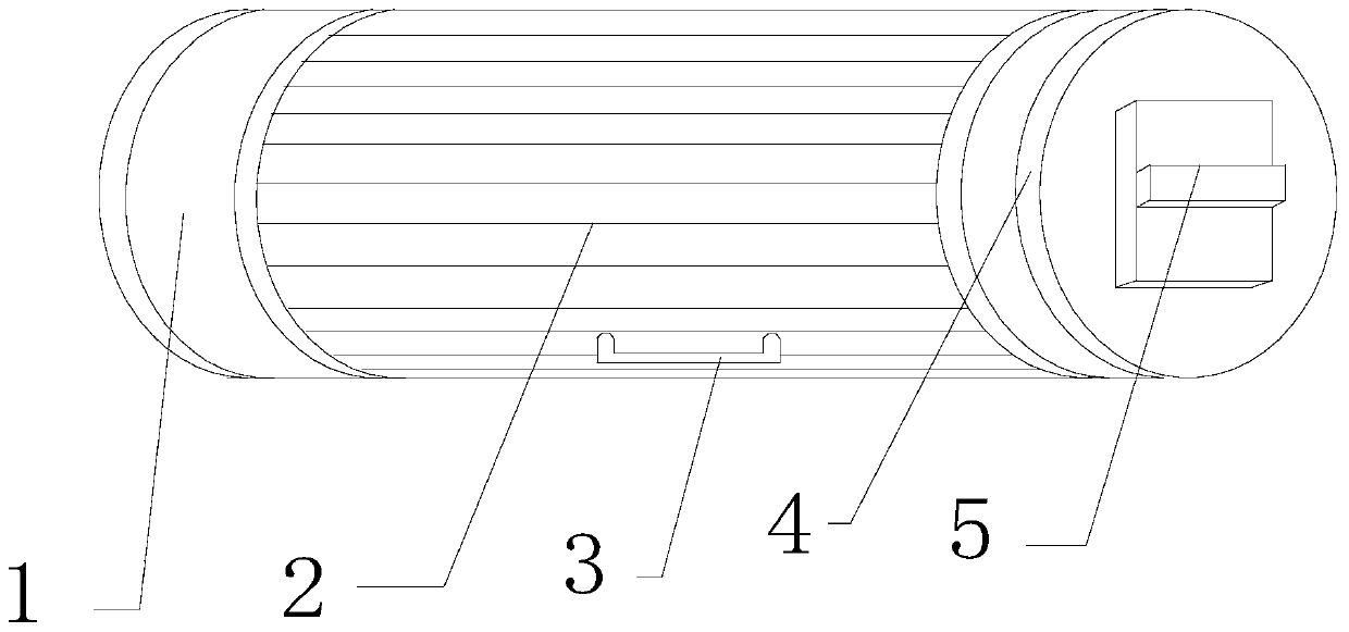
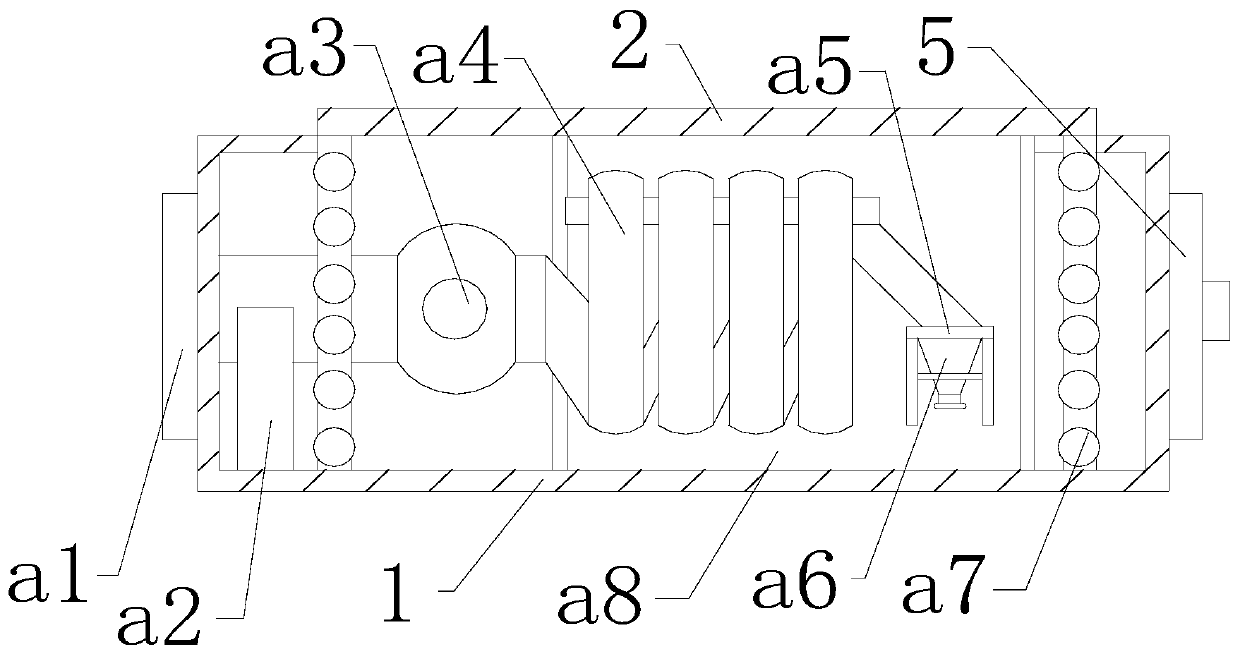
[0024] Such as Figure 1-Figure 5 Shown:

[0025] The present invention provides a fire-fighting equipment, the structure of which includes a body 1, a cabinet door 2, a handle 3, a fixing block 4, and a clamping plate 5. The clamping plate 5 cooperates with the fixing block 4 to be embedded and connected to both sides of the body 1, and the handle 3 Bolt connection at the front and bottom of the cabinet door 2. The cabinet door 2 is movably clamped in the middle of the body 1. The body 1 mainly includes a communication plate a1, a support frame a2, a water valve a3, a water pipe a4, an auxiliary frame a5, and a gun The head a6, the rotating device a7, and the pushing device a8, the connecting plate a1 is fixedly connected to the left side of the body 1, the water valve a3 is connected to the connecting plate a1 and is riveted to the upper end of the support frame a2, the rotating device a7 is movably connected to both sides of the body 1, the gun head a6 is fix...

Example Embodiment

[0031] Example 2

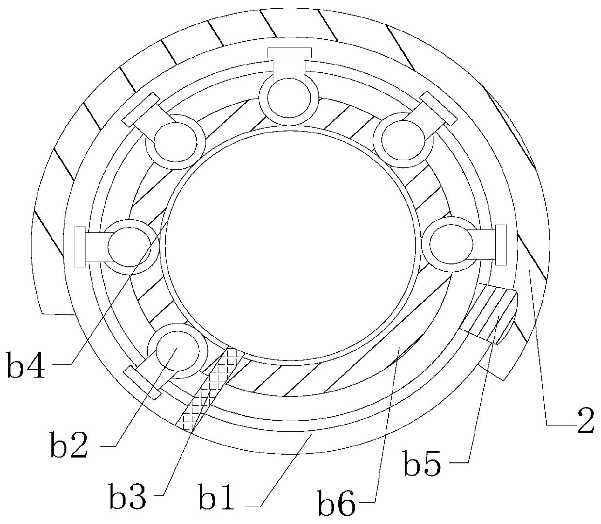
[0032] Such as Figure 6-Figure 7 Shown:

[0033] The present invention provides a fire-fighting equipment. The pushing device a8 mainly includes a pusher c1, an auxiliary plate c2, and a moving groove c3. The moving groove c3 is embedded and connected to the upper and lower ends of the machine body 1, and the auxiliary plate c2 is attached to At the front end of the pusher c1, the pusher c1 is embedded and connected above the moving groove c3 and is movably engaged with the rotating device a7. The auxiliary plate c2 is installed in clearance fit between the moving grooves c3, and the auxiliary plate c2 adopts The steel alloy material has a certain degree of toughness and sliding ability, so that the auxiliary frame a5 equipped with the gun head a6 can be installed at its side position, and the installation area is enlarged.

[0034] Wherein, the pusher c1 mainly includes a push plate c11, a spring c12, a pipe c13, a contact plate c14, a guide groove c15, a prote...


PUM


Abstract

The invention discloses fire-fighting equipment. The structure comprises a machine body, a cabinet door, a handle, a fixed block, and a clamping plate, wherein the cabinet door is movably clamped in the middle of the machine body, the machine body comprises a connecting plate, a support frame, a water valve, a water pipe, an auxiliary frame, a gun head, rotating devices and a pushing device, the rotating devices are movably connected with the two sides of the machine body, and the pushing device is movably clamped at the rear of a water pipe and the gun head. The equipment pushes the cabinet door upward by matching the handle to make the cabinet door be pushed in the machine body along a combined ring, and the condition that the cabinet door affects the use easily is avoided; a pushing block between the cabinet door and the combined ring is movably clamped with the pushing device, when the cabinet door rotates, the pushing block and a pusher are in riveted connection with a contact block, in a mobile room, a spring below the contact block pushes the pushing plate at one side outward along a guide tube, the pushing plate cooperates with a moving groove to push an auxiliary plate outward together, so that the firefighting equipment is exposed, and the use efficiency is improved further.

Description

technical field [0001] The present invention relates to the field of fire-fighting equipment, and more specifically, relates to a fire-fighting equipment. Background technique [0002] Fire-fighting equipment is a kind of equipment and equipment used for fire extinguishing, fire prevention and fire accidents, and the fire box is a kind of fire-fighting equipment that accommodates fire-fighting tools. When a fire or a dangerous fire source occurs, it is necessary to open the fire box and take out the fire-fighting tools to extinguish the fire. At present, the household fire box on the market needs to open the door when it is used, and take out the fire extinguisher, fire hose and other fire extinguishing equipment from the innermost part of the fire box. , it is easy to delay the fire fighting time, and when the fire hose is used to extinguish the fire, the door panel will move around due to the unfixedness, and it is easy to hit the fire hose continuously due to the surround...

Claims


Application Information

Patent Timeline
IPC IPC(8): A62C8/00A62C31/02
CPCA62C8/00A62C31/02
Inventor 曹志勇
Owner 临沂罗开投资有限公司
Why Eureka
Try Eureka